



Note: The (*) symbol indicates parts that must be pre-tightened and then finally tightened with the unloaded vehicle lowered onto the wheels.
Removal
To remove the rear suspension trailing arm, perform the following operations in sequence.
1. Remove the rear drum brake mechanism or rear disc brake mechanism.
2. Remove the rear wheel hub.
3. When removing the trailing arm, move the lift arm slightly toward the front of the vehicle so that it does not interfere with the operation.
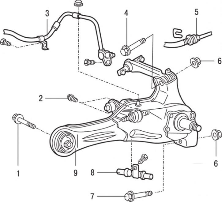
Fig. 16.11. Rear suspension trailing arm: 1* – bolt for fastening the longitudinal arm to the body (123 Nm); 2 – bolt connecting the correcting and longitudinal levers (34 Nm); 3 – rear wheel speed sensor (cars with ABS); 4 – bolt connecting the upper and longitudinal arms; 5 – brake hose; 6* – nut (98 Nm); 7 – bolt connecting the lower and longitudinal arms; 8 – Parking brake cable; 9 – Rear suspension trailing arm
4. Remove the spring retainer and disconnect the brake hose 5 from the lever (Fig. 16.11).
5. Loosen the two bolts and remove the rear wheel speed sensor (vehicles with ABS).
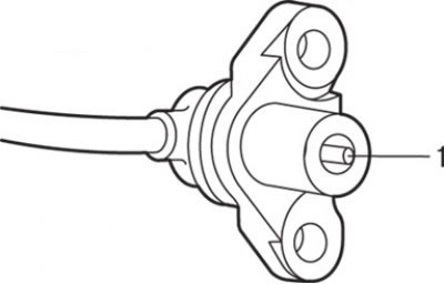
Fig. 16.12. Location of the pole piece (1) of the rear wheel speed sensor on vehicles with ABS
Caution! When removing the rear wheel speed sensor, be careful that the pole piece 1 (Fig. 16.12) of the sensor does not touch the surface of the rotor teeth or other parts.
6. Disconnect cable 8 (see Fig. 16.11) of the parking brake.
7. After installing the jack under the lower suspension arm, disconnect the fastening elements.
8. Unscrew and remove bolt 7 connecting the lower and longitudinal arms.
9. Unscrew and remove bolt 1 securing the trailing arm to the body.
10. Unscrew and remove bolts 2 securing the adjusting and longitudinal arms.
11. Unscrew the nut and remove bolt 4 connecting the upper and longitudinal arms.
12. Remove the longitudinal arm 9.
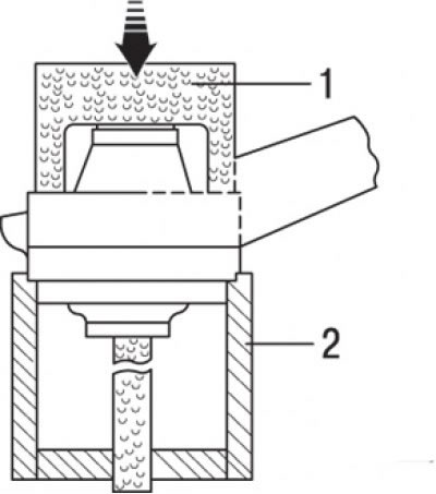
Fig. 16.13. Devices МВ991444 (1) and МВ991445 (2) for pressing out the bushing of the longitudinal arm
13. To press out the trailing arm bushing, use special tools (Fig. 16.13).
Examination
1. Check the rear suspension trailing arm for cracks and deformations.
2. Check the bushings for cracks, wear and damage.
Installation
Installation is carried out in the reverse order of removal, taking into account the following.
1. Correctly orient and position the trailing arm bushing.
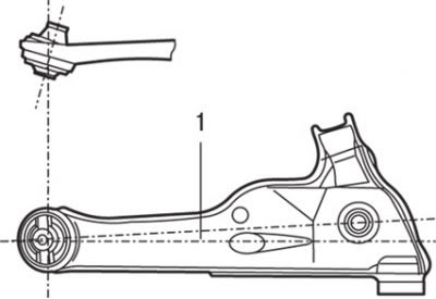
Fig. 16.14. When installing, the long protruding edge of the inner tube of the trailing arm bushing should be facing the inside of the car: 1 – longitudinal arm hole axis
2. Position the long protruding edge of the trailing arm inner bushing tube so that it faces the inside of the vehicle (Fig. 16.14).
3. Install the trailing arm bushing so that the bushing axis coincides with the axis of the trailing arm hole.
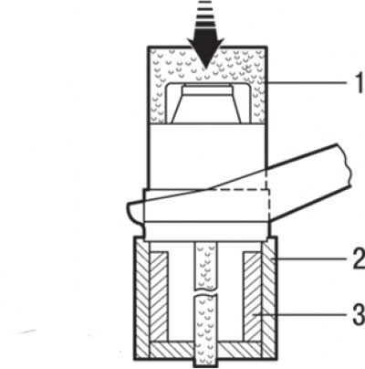
Fig. 16.15. Devices МВ991444 (1), МВ991445 (2) and МВ991446 (3) for pressing in the longitudinal arm bushing
4. Use special tools to press in the trailing arm bushing (Fig. 16.15).
5. When installing the wheel speed sensor, insert a flat feeler gauge into the gap between the end of the pole piece of the wheel speed sensor and the toothed surface of the rotor, then fix the sensor bracket in such a position that the gap around the entire circumference corresponds to a value of 0.3–0.9 mm.
Caution: Be careful not to damage the pole piece of the wheel speed sensor and the rotor teeth against other metal parts.
6. Install the rear drum brake mechanism or rear disc brake mechanism.
7. Install the rear wheel hub.