
Removing
To remove the anti-roll bar, perform the following steps in sequence.
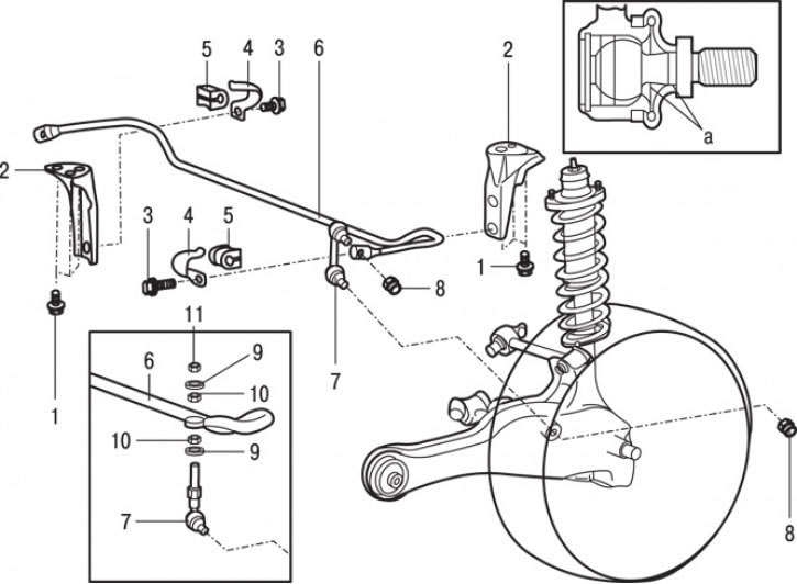
Pic. 16.21. Roll Stabilizer: a - places for applying lubrication; 1 - bolt (34 Nm); 2 – an arm of the stabilizer of cross stability; 3 - bolt (25 Nm); 4 - bracket for attaching the stabilizer bushing; 5 - bushing; 6 - stabilizer bar; 7 – a rack of the stabilizer of cross stability; 8 - nut (44 Nm); 9 - a cup of the rubber bushing of the anti-roll bar; 10 - rubber bushing of the anti-roll bar; 11 - self-locking nut
1. Turn away nuts and remove a rack 7 (pic. 16.21) anti-roll bar.
2. On models since 1999, unscrew the self-locking nut at the top of the stabilizer link, remove the cup and rubber bushing, then remove the stabilizer links and remove the rubber bushing and cup from it.
3. Turn away bolts 3 and remove bracket of fastening of the stabilizer bushing 4.
4. Remove sleeve 5.
5. Remove the anti-roll bar 6.
6. If necessary turn away three bolts 1 and remove an arm 2 of the anti-roll bar.
Examination
1. Check bushings for wear and damage.
2. Check the anti-roll bar for deformation or damage.
3. Check the anti-roll bar ball joint boots for cracks.
4. Check all bolts for wear and damage.
Installation
Installation is carried out in the reverse order of removal, taking into account the following.
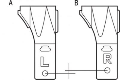
Pic. 16.22. The location of the brackets when installing the anti-roll bar: A - left, B - right brackets
1. As position of the right and left brackets of fastening of bushings of the stabilizer are various, installation of arms of the stabilizer of cross stability carry out according to fig. 16.22.
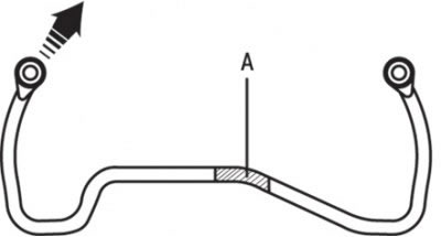
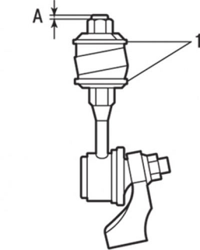
Pic. 16.23. Identification label location (A) on the stabilizer
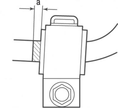
Pic. 16.24. Mutual arrangement of the bushing and the identification mark of the stabilizer: a = 5 mm
2. Position the stabilizer so that the identification mark is on the right side of the vehicle (pic. 16.23). Then install the bushing so that the identification mark protrudes from the bushing by approximately 5 mm from the inside (pic. 16.24).
Pic. 16.25. Proper placement of cups (1) anti-roll rubber bushing: A = 3–5 mm
3. On models since 1999 of release check up that cups of the rubber plug of the anti-roll bar are located as shown in fig. 16.25, and tighten the self-locking nut so that the A value is between 3 and 5 mm.
4. Check rear wheel alignment.