



2. Turn off the ignition and connect the MUT-II device to the diagnostic connector.
3. Connect the stroboscope to the high-voltage wire (contact No.1) of ignition coil No.1 (Fig. 2.6).
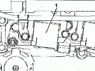
Fig. 2.6. Location of the crankshaft position sensor connector
Note: Ignition coil #1 high voltage wire is looped and longer than the other high voltage wires.
4. Start the engine and let it idle.
5. Using the MUT-II device, check the idle speed, which should correspond to the nominal value.
Engine crankshaft speed at idle: 600±100 min⁻¹*
Note
(1) *: The engine idle speed of a vehicle with a manual transmission changes in accordance with the transmission oil temperature.
(2) After 4 minutes of engine idling, the engine crankshaft speed should be approximately 750 min⁻¹ (Fig. 27).
6. On the MUT-II, select Actuator test
Note: At this time, the engine speed should be about 750 min⁻¹
7. Check the setting of the main ignition timing angle, which should correspond to the nominal value.
Setting the ignition timing angle: 5° ±3° before TDC
8. If the basic ignition timing setting is not as required, check the GO system.
9. On the MUT-II device, press the "Cancel forced activation of actuators" button (Select a forced driving cancel mode) and cancel the "Actuator test" mode.
Warning: If the test mode is not cancelled, the forced actuator actuation mode will continue for 27 minutes. Driving the vehicle under these conditions may cause engine damage.
10. Check that the basic ignition timing setting is within acceptable limits.
Basic setting of ignition advance angle: 16° before TDC
Notes
(1) The ignition timing will be set to about 6° BTDC after 4 minutes of operation after the basic ignition timing check is cancelled.
(2) The ignition timing angle fluctuates around ±7° BTDC even under normal operating condition.
(3) When the engine crankshaft speed increases, the ignition timing angle can change within 5° of the nominal value.
11. Remove the strobe light.
12. Turn off the ignition and disconnect the MUT-II device.