



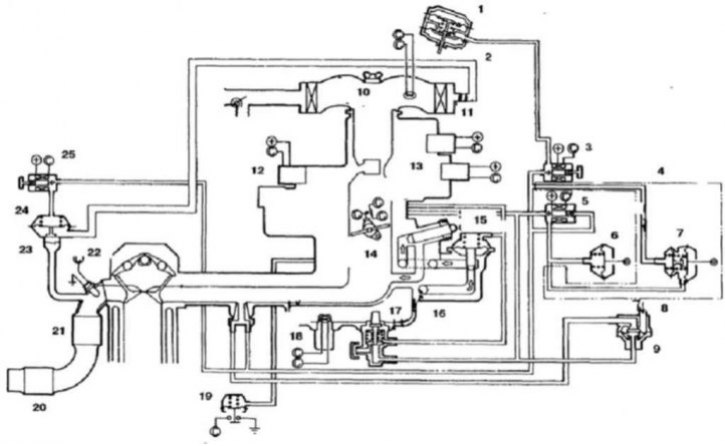
13.1a Carburetor Engine Feedback System - Early Models
1. Damper; 2. Fast idle system diaphragm; 3. Fast idle speed solenoid valve; 4. For models with 4-speed manual transmission; 5. Ignition distributor electromagnetic valve; 6. Ignition distributor; 7. Double diaphragm; 8. From the carbon filter; 9. Blow-off valve; 10. Incoming air temperature sensor; 11. Injection valve; 12. Enrichment valve; 13. Fuel shut-off valve; 14. Throttle position sensor; 15. Additional control valve; 16. Exhaust gas recirculation system control valve; 17. Temperature valve; 18. Coolant temperature sensor; 19. Vacuum switch; 20. Catalytic converter; 21. Catalytic converter; 22. Oxygen content sensor; 23. Plate valve; 24. Air valve; 25. Additional air valve
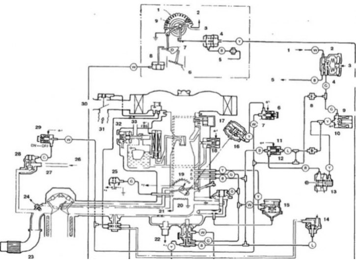
13.1b Carburetor Engine Feedback System - Late Models
Automatic air damper mechanism
1. Heating element; 2. To the air damper relay; 3. Air damper; 4. Breaker; 5. To the intake manifold; 6. Throttle valve; 7. Fast idle cam; 8. Air damper opening diaphragm; 9. Bimetallic spiral
Carburetor feedback system
1. From the carburetor; 2. Low atmospheric pressure compensation system diaphragm; 3. Atmospheric pressure; 4. Low pressure - high pressure; 5. To the primary chamber of the carburetor; 6. Throttle opening solenoid valve; 7. On-Off; 8. Check valve; 9. On-Off; 10. Solenoid valve of the ignition advance system when the engine is cold; 11. Ignition advance system electromagnetic valve; 12. On-Off; 13. Distributor; 14. From the carbon filter; 15. Vacuum diaphragm; 16. Damper and throttle opening diaphragm; 17. Fuel mixture control valve; 18. Fuel shut-off valve; 19. Throttle position sensor; 20. Heating element; 21. To the heating element relay; 22. Coolant temperature sensor; 23. Catalytic converter; 24. Oxygen content sensor; 25. Vacuum diaphragm; 26. From the air filter; 27. Plate valve; 28. Air valve; 29. Additional air valve; 30. Cold air; 31. Hot air; 32. Float chamber ventilation valve; 33. To the carbon filter
(The original was published on the website: MITSUBISHIMAN.ru)
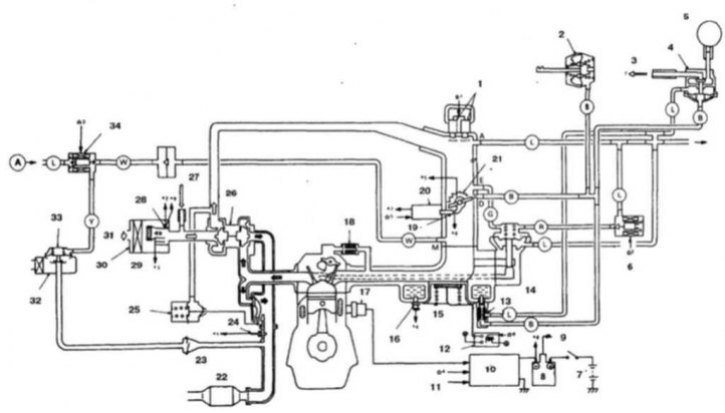
13.1c Schematic diagram of the dual-point fuel injection system (turbocharged model shown, system diagram for non-turbocharged models is similar)
1. Fuel injectors; 2. Distributor; 3. Blow-off air; 4. Crankcase ventilation valve; 5. Carbon filter; 6. Exhaust gas recirculation solenoid valve; 7. Battery; 8. Ignition coil; 9. To the distributor; 10. Igniter; 11. Signal from the distributor; 12. Fuel mixture heater relay; 13. Temperature valve; 14. Exhaust gas recirculation valve; 15. Cold fuel mixture heater; 16. Coolant temperature sensor; 17. Fuel knock sensor; 18. Crankcase ventilation valve; 19. Idle switch; 20. Vacuum diaphragm; 21. Oxygen content sensor; 22. Catalytic converter; 23. Plate valve; 24. Oxygen content sensor; 25. Bypass valve; 26. Turbocharger; 27. Air; 28. Air flow sensor; 29. Air temperature sensor; 30. Air filter; 31. Air intake; 32. Additional air filter; 33. Air valve; 34. Additional air valve
1. The electronic engine control system consists of three types of elements (13.1a, 13.1b and 13.1c):
- a) Information sensors (send information to the electronic control unit)
- b) Electronic control unit
- c) Solenoid valves and relays (receive control signals from the electronic control unit)
2. If you detect any faults in the system, contact specialists.