
WARNING: Additional fault codes may be generated during certain test procedures. You need to be careful, as the codes issued during the verification process can mislead the inspector. After the end of the checks, all codes must be erased.
Analog Voltmeter Method
Connect an analog voltmeter to pins A and B on the self-diagnosis plug.
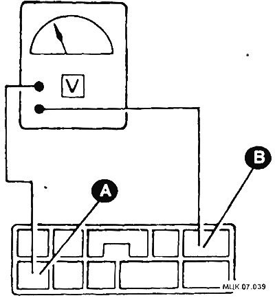
A - ground contact; B - self-diagnosis contact.
Turn on the ignition. If one or more fault codes are stored in the memory of the electronic control module, the voltmeter needle will begin to oscillate between two voltage values. If there are no fault codes in the memory, the arrow will stand still.
CAUTION: If the voltmeter does not behave as described, reverse the polarity of the connection to the self-diagnosis plug.
- the first series of hand swings define tens, the second series of hand swings define units;
- the voltmeter needle will deviate for a longer period of time, showing tens and for a shorter period of time, showing units;
- if there are no fault codes, the arrow will only show periodic on and off impulses (fluctuations).
Count the number of swings of the hand in each series and write down the code. To determine the meaning of the fault code, refer to the tables at the end of the chapter.
Continue reading codes until all stored codes have been read and written.
Turn off the ignition and disconnect the voltmeter to finish reading the codes.
LED probe method
Connect the LED probe between pins A and B on the self-diagnosis plug.
Turn on the ignition. If one or more trouble codes are stored in the memory of the electronic control module, the LED will flash to determine the trouble codes.
CAUTION: If the LED does not flash as described, reverse the polarity of the LED connection to the self-diagnosis plug.
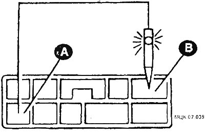
A - ground contact; B - self-diagnosis contact.
- the first series of flashes define tens, the second series of flashes define ones;
- tens are determined by 1.5 seconds with flashes separated by short pauses of 0.5 seconds;
- A 2-second pause separates each series of flashes that define tens and ones;
- units are defined by 0.5 second flashes separated by short pauses of 0.5 seconds;
- four long and one short flash, for example, correspond to code 41;
- if there are no fault codes, then the LED turns on and off 8 times with pauses of 0.5 seconds.
Count the number of flashes in each series and write down the code. To determine the meaning of the fault code, refer to the tables at the end of the chapter.
Continue reading codes until all codes stored in memory have been read and written.
Turn off the ignition and disconnect the LED probe to finish reading the codes.