



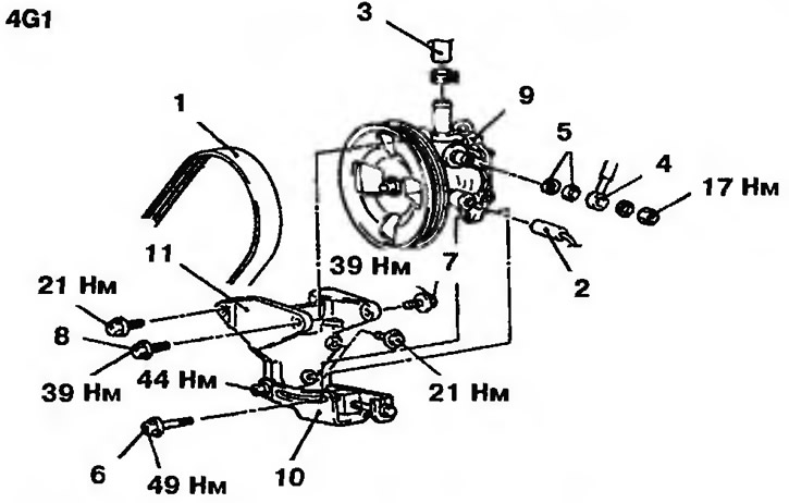
Figure 13.17a. Power steering pump for vehicles with 4G1 engines: 1 - Pump drive belt; 2 - Pressure sensor wiring connector; 3 - Intake hose; 4 - Delivery hose; 5 - Sealing rings; 6, 7, 8 - Bolts; 9 - Power steering pump; 10 - Pump support; 11 - Pump mounting bracket
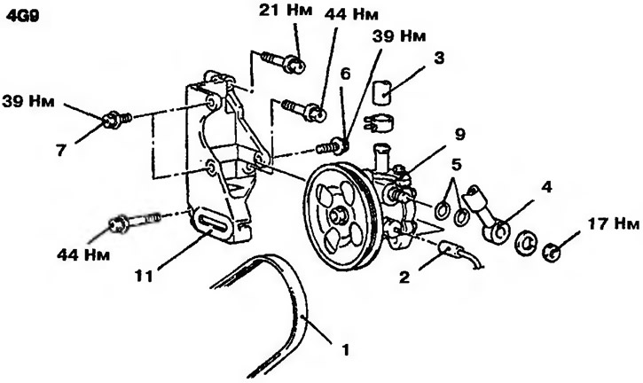
Figure 13.176. Power steering pump for vehicles with 4G9 engines: 1 - Pump drive belt; 2 - Pressure sensor wiring connector; 3 - Intake hose; 4 - Delivery hose; 5 - Sealing rings; 6, 7 - Bolts; 9 - Power steering pump; 11 - Pump mounting bracket
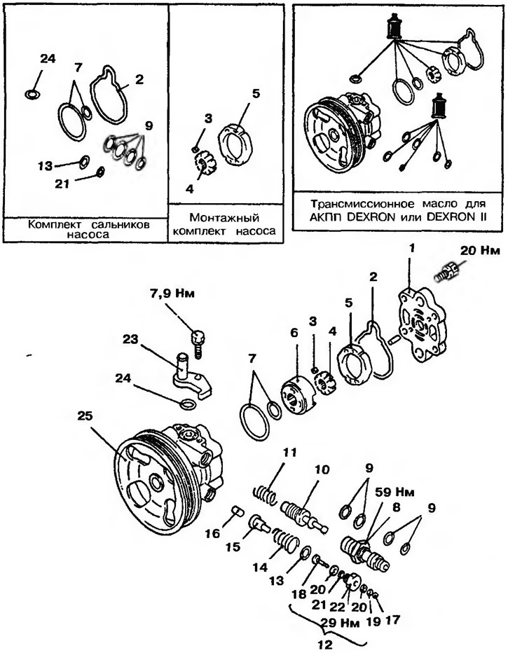
Figure 13.18. Disassembled power steering pump: 1 - Pump cover; 2, 7, 9, 13, 21, 24 - Sealing rings; 3 - Rotor blade; 4 - Rotor; 5 - Cam cage; 6 - Disc, 8, 23 - Adapters; 10 - Pressure reducing valve; 11 - Pressure reducing valve spring; 12 - Plug (assembled); 14 - Spring; 15 - Piston; 16 - Piston rod; 17 - Snap ring; 18 - Plug; 19 - Washer; 20 - Damper; 22 - Cork; 25 - Oil pump housing with pulley
Attention! The manufacturer does not recommend disassembling the pressure reducing valve.
Installing the disk
1. Install the disc so that the threaded hole in the pump and the rod holes of the disc are in line (Figure 13.19).
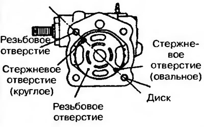
Figure 13.19. Install the disc so that the threaded hole in the pump and the disc rod holes are in line
Installing the cam cage
2. The cam cage is installed by punching towards the disk (Figure 13.20).
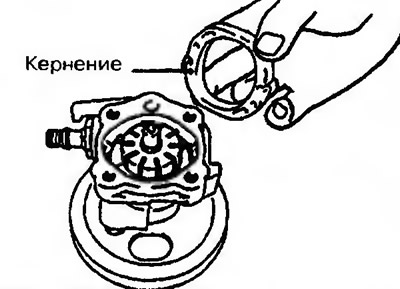
Figure 13.20. The cam cage is installed by punching towards the disk
Installing rotor blades
3. The rotor blade is mounted on the rotor in strict compliance with the installation position (Figure 13.21).
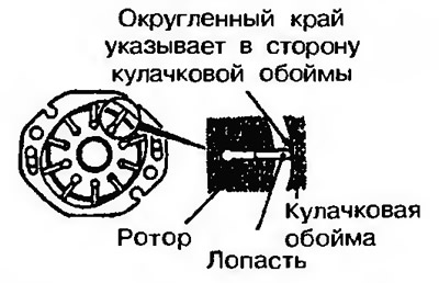
Figure 13.21. The rotor blade is mounted on the rotor with strict observance of the mounting position
[The text of the article was obtained from the website MITSUBISHIMAN]