



Contents: Adjusting the gear torque ⤓ Aligning the lock washer with the…⤓ Installation of the clamp ⤓
Adjusting the gear torque
8. Set the toothed rack to the middle position. Tighten the stop cover to a torque of 15 Nm.
9. Rotate the pinion shaft from the neutral position clockwise one revolution using the special tool MB991006. Then rotate the stop cover back 30"-60" and adjust the torque (Figure 13.11).
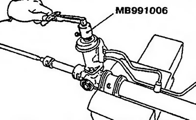
Figure 13.11. Rotate the pinion shaft from the neutral position clockwise one revolution using the special tool MB991006. Then rotate the stop cover back 30°-60° and adjust the torque
10. Rotate the gear one revolution using the special tool MB991006 and check the torque (Figure 13.12).
Nominal value: 0.6-1.4 Nm. Torque deviation: 0.4 Nm.
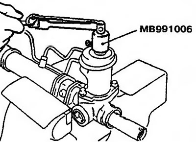
Figure 13.12. Rotate the gear one revolution using the special tool MB991006 and check the torque
Attention! When adjusting, the nominal value is set to the maximum value. Make sure that the toothed rack moves continuously and does not jam.
11. After adjustment, secure the stop cover with the lock nut.
Aligning the lock washer with the steering rod
12. After assembling the steering rod and toothed rack, center the lock washer plates in the steering rod groove (in two places) (Figure 13.13).
Installation of the clamp
13. Using the adjusting bolt of the special tool MB991561, adjust the hole size W to the nominal value (Figure 13.14).
[The article was obtained from this portal mitsubishiman.ru]
Nominal value W: 2.9 mm.
If more than 2.9 mm, tighten the adjusting bolt. If less than 2.9 mm, loosen the adjusting bolt.
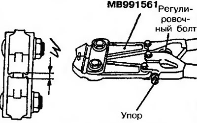
Figure 13.14. Using the adjusting bolt of the special tool MB991561, adjust the hole size W to the nominal value
Attention! The dimension W changes by 0.7 mm with each turn of the bolt. The adjusting bolt moves no more than one full turn.
14. Compress the clamp with a special tool МВ991561 (Figure 13.15).
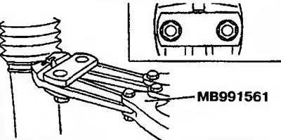
Figure 13.15. Compress the clamp with a special tool МВ991561
Caution: Fix the steering gear and compress the clamp with a special tool until the special tool touches the stop.
15. Check that the width of the pressing A corresponds to the nominal value (Figure 13.16). Nominal value: 2.4-2.8 mm.
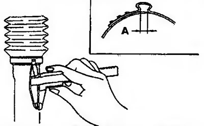
Figure 13.16. Check that the width of the pressing A corresponds to the nominal value
If the width of the pressing A is more than 2.8 mm
Adjust the W size using the following formula:
W = 5.5 mm - A (for example: if A is 2.9 mm, then W is 2.9 mm).
If the width of the pressing A is less than 2.4 mm
Remove the clamp and adjust the W dimension using the following formula:
W = 5.5 mm - A (for example: if A is 2.3 mm, then W is 3.2 mm).
Then, using a new clamp, repeat steps 15 and 16.