



Contents: Disassembly ⤓ Assembly ⤓
Disassembly
Removal of the ball bearing is shown in Figure 11.44, removal of the tapered roller bearing is shown in Figure 11.45, and removal of the pin is shown in Figure 11.46. The pin is pushed out through hole A in the differential housing using a punch.
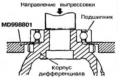
Figure 11.44. Removing the ball bearing | 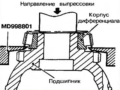
Figure 11.45. Removing a tapered roller bearing |
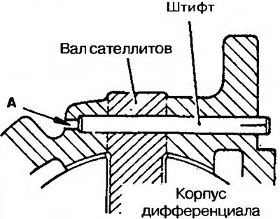
Figure 11.46. Removing the pin
Assembly
Adjusting washers, bevel gears of half-axles, satellites and satellite shaft
1. Install adjusting washers on the back side of the bevel gears of the axle shafts and insert the satellites into the differential housing.
Attention! When installing a new bevel gear of the axle shaft, an adjusting washer of medium thickness (0.93-1.00 mm) is used.
2. Install the adjusting washers on the back side of the satellites, and then, by rotating them, engage them with the bevel gears of the axle shaft, after which both satellites are set to the required position (Figure 11.47).
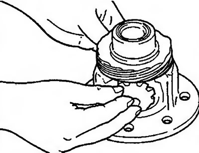
Figure 11.47. Installing adjusting washers, bevel gears and satellites
The original can be found on the website (MitsubishiMan)
3. Install the satellite shaft (Figure 11.48).
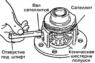
Figure 11.48. Installing the satellite shaft
4. Check the clearance of the teeth of the bevel gear of the axle shaft and the differential satellite (Figure 11.49). Nominal value: 0.025-0.150 mm.
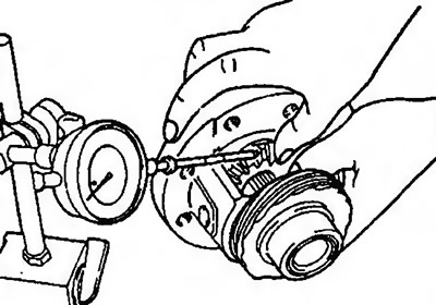
Figure 11.49. Checking the clearance of the bevel gear teeth of the axle shaft and the satellite
5. If the tooth profile clearance does not correspond to the nominal value, the bevel gears must be removed again. Install an adjusting washer of the correct size and install the gears again.
Caution! Both bevel gears of the axle shaft must be adjusted with the same tooth profile clearance.