
English Русский
Български
Беларускі
Український
Српски
Hrvatski
Română
Polski
Slovenský
Magyar
Articles Bookmark Contacts Sitemap   
Company Audi Company Ford Company Hyundai Company Kia Company Mazda Company Mercedes-Benz Company Nissan
MitsubishiMan.ru


Home Colt Lancer Galant L200 Outlander Pajero Others
Pajero 4 (2006-2021) Pajero 1 and 2 (1982-1999)

Removal the hub and steering knuckle (Mitsubishi Pajero 4)

  • Home
  • Pajero
  • 4 (2006-2021)
  • Transmission
  • Drive shafts
  • Removal the hub and steering knuckle
0
Contents: Short wheelbase ⤓ Long wheelbase ⤓

Short wheelbase
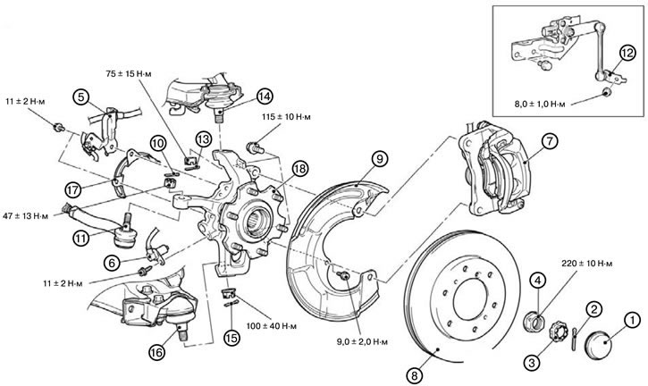


Short wheelbase


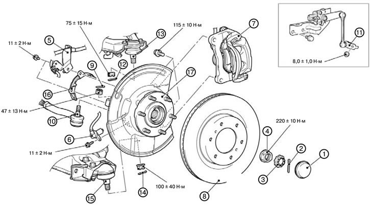
1. Remove the hub cover (1).

2. Remove the cotter pin (2).

3. Remove the axle cover (3).

4. Unscrew the axle nut (4).

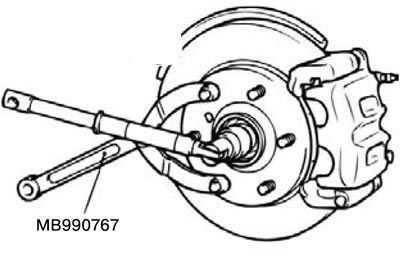
Caution: Do not load the front wheel hub bearing with the weight of the vehicle when loosening the wheel drive axle nut.
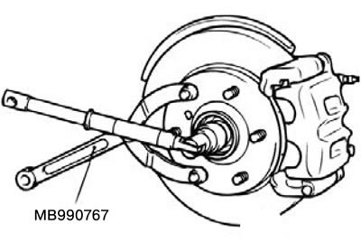


5. Remove the brake hose bracket (5).

6. Remove the wheel speed sensor (6).

7. Remove the caliper assembly (7).

Note: Secure the removed caliper assembly with wire so that it does not fall.


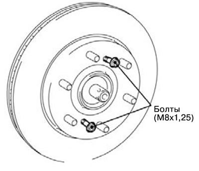
8. Remove the brake disc (8).

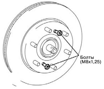
Note: If removing the brake disc is difficult, install the M8x1.25 bolts as shown in the figure and remove the brake disc by tightening the installed bolts.


9. Remove the dust cover (9).


10. Remove the cotter pin (10).

11. Disconnect the connection of the tie rod end, hub and steering knuckle assembly (11).

12. Remove the front vehicle height sensor and disconnect the upper suspension arm connection (12).

13. Remove the cotter pin (13).

14. Disconnect the upper control arm, hub and steering knuckle assembly (14).

15. Remove the cotter pin (15).

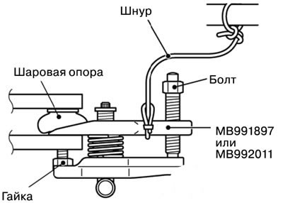
16. Disconnect the lower suspension arm, hub and steering knuckle assembly connection (16).

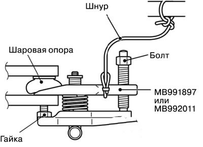
Caution: Use a special tool to loosen the nut. The nut should be loosened, but not completely removed. To prevent the puller from slipping off, it is necessary to first tie it with a cord or wire.


17. Remove the rotor guard (17).

18. Remove the hub and steering knuckle assembly (18).

Long wheelbase


Long wheelbase


1. Remove the hub cover (1).

2. Remove the cotter pin (2).

3. Remove the axle cover (3).

4. Unscrew the axle nut (4).

Caution: Do not load the front wheel hub bearing with the weight of the vehicle when loosening the wheel drive axle nut.


5. Remove the brake hose bracket (5).

6. Remove the wheel speed sensor (6).

7. Remove the caliper assembly (7).

Note: Secure the removed caliper assembly with wire so that it does not fall.


8. Remove the brake disc (8).

Note: If removing the brake disc is difficult, install the M8x1.25 bolts as shown in the figure and remove the brake disc by tightening the installed bolts.


9. Remove the cotter pin (9).

10. Disconnect the tie rod end, hub and steering knuckle assembly connection (10).


11. Remove the front vehicle height sensor and disconnect the upper suspension arm connection (11).

12. Remove the cotter pin (12).

13. Disconnect the upper suspension arm, hub and steering knuckle assembly connection (13).

14. Remove the cotter pin (14).

15. Disconnect the lower suspension arm, hub and steering knuckle assembly connection (15).

Caution: Use a special tool to loosen the nut. The nut should be loosened, but not completely removed. To prevent the puller from slipping off, it is necessary to first tie it with a cord or wire.


9. Remove the cotter pin (9).

10. Disconnect the tie rod end, hub and steering knuckle assembly connection (10).

11. Remove the front vehicle height sensor and disconnect the upper suspension arm connection (11).

12. Remove the cotter pin (12).

13. Disconnect the upper suspension arm, hub and steering knuckle assembly connection (13).

14. Remove the cotter pin (14).

15. Disconnect the lower suspension arm, hub and steering knuckle assembly connection (15).

Caution: Use a special tool to loosen the nut. The nut should be loosened, but not completely removed. To prevent the puller from slipping off, it is necessary to first tie it with a cord or wire.
This article is available at: russian, bulgarian, belarusian, ukrainian, serbian, croatian, romanian, polish, slovak, hungarian
This article was reviewed by: Miroslav Rakov
Share with friends:
◀ Previous
Pajero 4: Drive shafts
Next ▶

Rear axle oil change
Checking the oil level in the rear axle
Checking the rear axle play
Replacing the hub bolt
Checking the resistance force to rotation of the rear wheel hub bearing
Installing the hub and steering knuckle
Checking the resistance moment of the front wheel hub bearing rotation start
Checking the axial clearance in the front wheel hub bearing
Disassembling the hub and steering knuckle
Assembly of the hub and steering knuckle
Similar materials for other Mitsubishi models

➤ Steering knuckle and hub — removal and installation Mitsubishi Colt 2 and 3 (1983-1993)
➤ Steering / Front Wheel Drive Mitsubishi Lancer 3 and 5 (1984-1992)
➤ Steering knuckle and hub — removal and installation Mitsubishi Galant 5 (1983-1989, petrol)
➤ Steering column turn signal switch Mitsubishi L200 4 (2005-2014, diesel)
➤ Locking and unlocking the steering wheel Mitsubishi Outlander 1 (2003-2008)
➤ Steering wheel adjustment Mitsubishi Carisma (1995-2004)
Link in different formats to this article
Comments and feedback from visitors
No comments yet


Add up two numbers 18 + 23


Pajero 4 (2006-2021) 
  • General information
  • User manual
  • Troubleshooting
  • Maintenance
  • Technical specifications
  • Power unit
  • Engine repair
  • Cooling system
  • Lubrication system
  • Fuel system
  • Engine management system
  • Intake and exhaust system
  • Engine electrical equipment
  • Transmission
  • Clutch
  • Manual gearbox
  • Automatic gearbox
  • Drive shafts
  • Chassis and running gear
  • Front suspension
  • Rear suspension
  • Brake system
  • Steering
  • Body and interior
  • Exterior (external elements)
  • Interior (internal elements)
  • Doors, locks and windows
  • Body dimensions
  • Electrical equipment
  • Safety system (SRS)
  • Air conditioner
  • Equipment and devices
  • Electrical diagrams
Pajero 1 and 2 (1982-1999) 
  • General information
  • User manual
  • Seats and seat belts
  • Instruments and controls
  • Driving and operation
  • Maintenance
  • Power unit
  • Gasoline engines
  • Diesel engines
  • Ignition system
  • Engine electrical equipment
  • Cooling and lubrication system
  • Power and exhaust system
  • Fuel system (gasoline)
  • Fuel system (diesel)
  • Transmission
  • Clutch
  • Mechanical gearbox
  • Automatic gearbox
  • Drive shafts and axles
  • Chassis and running gear
  • Front suspension
  • Rear suspension
  • Steering
  • Brake system
  • Body and interior
  • Exterior (external elements)
  • Interior (internal elements)
  • Doors, locks and windows
  • Electrical equipment
  • Equipment and devices
  • Heater and air conditioner
  • Cruise control
  • Headlights and lighting
  • Electrical circuits
MitsubishiMan.ru © 2018–2026 • Mobile version • Articles about Mitsubishi • Contacts • Sitemap: EN BG BY UA RS HR RO PL SK HU • Site search • Bookmark
Colt 2 and 3 (1983-1993) · Colt 4 and 5 (1991-2003) · Colt 5 (1995-2003) · Lancer 3 and 5 (1984-1992) · Lancer 9 (2000-2007) · Galant 5 (1983-1989) · Galant 6 and 7 (1987-1998) · L200 4 (2005-2014) · Outlander 1 (2003-2008) · Pajero 1 and 2 (1982-1999) · Pajero 4 (2006-2021) · Carisma (1995-2004) · Space Star (1998-2005) ·
This resource sets cookies 🍪 to avoid bothering you with repeated data entry.