



Removal
- Raise the rear of the vehicle and support it on stands,
- Loosen the nuts and remove the anti-roll bar (Fig. 14.74).
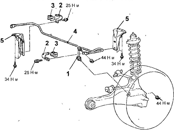
Fig. 14.74. Anti-roll bar: 1 - stabilizer bar for lateral stability; 2 - stabilizer bushing mounting bracket; 3 - bushing; 4 - anti-roll bar; 5 - anti-roll bar bracket
- Unscrew the bolts and remove the stabilizer bushing mounting brackets.
- Remove the anti-roll bar.
- If necessary, unscrew 3 bolts and remove the stabilizer bar brackets.
Examination
- Check the bushings for wear and deterioration.
- Check the anti-roll bar for bending or damage.
- Check the dust covers of the ball joints of the stabilizer bars for cracks.
- Check all bolts for wear or damage.
- Checking the torque required to turn the ball joint pin of the anti-roll bar
- Shake the ball joint pin of the anti-roll bar several times from side to side. Install a special tool on the ball joint pin and use a torque wrench to measure the initial torque required to rotate the ball joint pin of the pairwise stability stabilizer bar (Fig. 14.75).
(Article reprinted from the website: mitsubishiman)
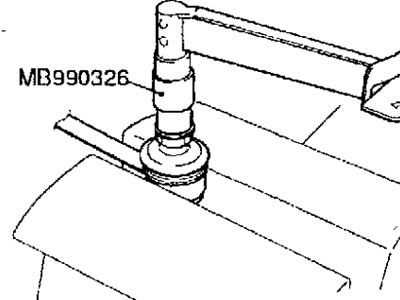
Fig. 14.75. Measuring the torque required to rotate the ball joint pin of the anti-roll bar
Torque: 1.7-3.1 Nm
- If the torque exceeds the permissible values, replace the stabilizer bar strut.
- If the torque is significantly below the permissible value; the ball joint can be used repeatedly as long as it does not bind or have excessive play.
- Checking the dust cover of the anti-roll bar ball joint
- Use your fingers to squeeze the dust cover and check for cracks or damage.
- If the dust cover is cracked or damaged, replace the stabilizer bar link.
- Replacing the anti-roll bar ball joint dust cover
- Only if the dust cover is damaged accidentally during vehicle maintenance, replace it as follows.
- Using a screwdriver blade, remove the spring ring and dust cover from the ball joint of the anti-roll bar (Fig. 14.76).
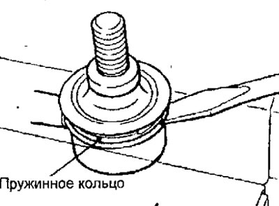
Fig. 14.76. Using a screwdriver to remove the ball joint protective boot retaining spring ring
- Apply general purpose grease to the inside surfaces of the new dust cover (Fig. 14.77).
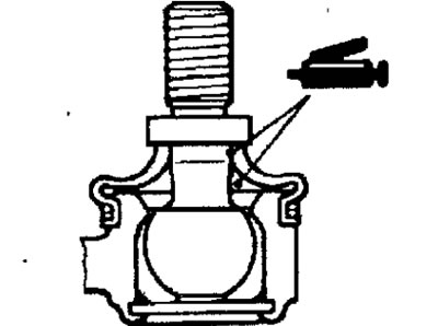
Fig. 14.77. Lubricant application points on the inner surfaces of the new anti-roll bar dust cover
- Wrap the ball joint pin with plastic tape and install the dust cover on the joint.
- Install the dust cover retaining spring ring.
- Use your fingers to squeeze the dust cover and check for cracks or damage.
Installation
- Installation is carried out in the reverse order of removal, taking into account the following.
- Since the positions of the right and left anti-roll bar brackets are different, install them in accordance with the markings on the brackets (Fig. 14.78).
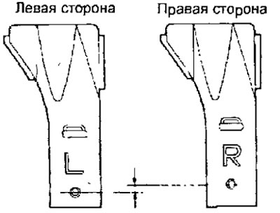
Fig. 14.78. Location of markings on the stabilizer bar brackets
- Check the rear wheel alignment angles.