



| Code | Malfunction |
| 11 | Short circuit in the electrical circuit of the throttle position sensor |
| 12 | Open circuit of the throttle position sensor. |
| 14 | Throttle Position Sensor Mismatch |
| 15 | Transmission Fluid Temperature Sensor Circuit Open |
| 21 | Open circuit of crankshaft angle sensor |
| 22 | Short circuit/open circuit in input shaft sensor |
| 23 | Short circuit/open circuit in output shaft sensor circuit |
| 25 | Short circuit in the wide open throttle position sensor circuit |
| 26 | Damage to the brake light switch circuit |
| 31 | Low and reverse solenoid valve circuit failure |
| 32 | Damage to the downshift solenoid valve circuit |
| 33 | Damage to the second gear solenoid valve target |
| 34 | Damage to the target of the overdrive solenoid valve |
| 36 | Damage to the clutch damper solenoid valve circuit |
| 41 | 1st gear ratio is out of specification |
| 42 | 2nd gear ratio is out of specification |
| 43 | 3rd gear ratio is out of specification |
| 44 | 4th gear ratio is out of specification |
| 46 | Reverse gear ratio is out of specification |
| 51 | Communication failure with the electronic control unit |
| 52 | The clutch damper solenoid valve is faulty |
| 54 | Short circuit to ground/open circuit of automatic transmission control relay |
| 56 | Short circuit to ground of the N position indicator lamp of the automatic transmission selector lever |
1. Take a trip to warm up the gearbox to a temperature of 70-80°C.
Note
- 1) Measure the transmission fluid temperature using the MUT-II device.
- 2) Referring to the diagram shown in Figure 13.8, determine the transmission fluid level, since it will take some time for the fluid to warm up to a temperature of 70-80°C.
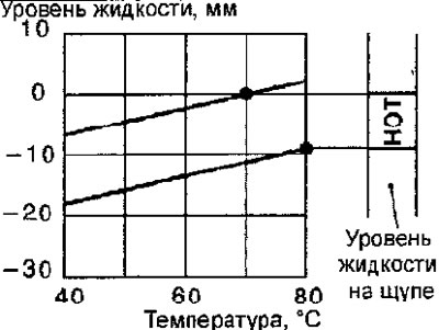
Fig. 13.8. Transmission fluid level vs. temperature diagram
2. Park the car on a level, horizontal surface.
The article was taken from the website MITSUBISHIMAN.ru
3. With the engine running, move the selector lever from position N to all positions and back to position N.
4. Before removing the dipstick, wipe off any dirt from the area around the dipstick. Remove the dipstick and check the condition of the transmission fluid. Check the color of the automatic transmission fluid. Check the automatic transmission fluid for unusual odors. Compare the fluid to fresh fluid to determine if the color or odor has changed.
Note: If the automatic transmission fluid has a burnt odor or is contaminated with particles from bushing material or friction, a major transmission overhaul may be required, as well as a flush of the heat exchanger and tubes.
5. Check the fluid level, which should be between the HOT marks (Fig. 13.9). If necessary, add the required amount of fluid. A low fluid level can be the cause of many malfunctions, since air gets into the fluid, and the suspension of fluid with air becomes compressible, which leads to an erratic change in pressure and disruption of the clutches and band brakes. Also, an increased fluid level causes the rotating gears of the gearbox to whip up foam, which leads to the same results as air getting into the transmission fluid. In any case, air bubbles lead to overheating and oxidation of the transmission fluid, which, getting into the valves, disrupts the clutch and brakes. Foaming can lead to fluid leakage, which can be mistaken for a fluid leak.
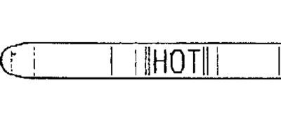
Fig. 13.9. Location of the HOT marks on the transmission fluid level dipstick
Transmission fluid: Dia Queen ATF SP II M or ATF SP III
6. Insert the transmission fluid dipstick securely.