



Note: On cars with 4G93, F9Q1 engines since 2000, a clutch pedal position switch is installed instead of the adjusting bolt.
Removal
- On a left-hand drive vehicle, remove the relay box and activated carbon canister.
- Loosen the clutch master cylinder mounting nut (Fig. 11.6).
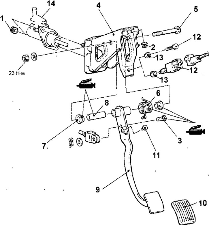
Fig. 11.6. Clutch pedal: 1 - master cylinder mounting nut, 13 Nm; 2 - nut, 25 Nm; 3 - pin; 4 — clutch pedal bracket; 5 - bolt; 6 - return spring; 7 - clutch pedal bushing; 8 - tube; 9 — clutch pedal; 10 - rubber pad of the clutch pedal; 11 - emphasis; 12 - adjusting bolt or clutch release sensor, 13 Nm; 13 - lock nut, 13 Nm; 14 - clutch master cylinder
- Loosen the clutch master cylinder bracket mounting nut.
- Remove the cotter pin, washer and stud securing the clutch cylinder pushrod to the clutch pedal.
- Remove the pedal bracket and clutch pedal assembly.
- Loosen the nut and remove the bolt securing the clutch pedal to the bracket.
- Remove the return spring.
- Remove the bushing from the clutch pedal tube.
- Remove the clutch pedal tube.
- Remove the clutch pedal from the bracket.
- Remove the rubber pad from the clutch pedal.
- Remove the stop.
- Loosen the lock nut and remove the adjusting bolt or clutch release sensor.
Examination
- Check the pedal arm and bushing for wear.
- Check the clutch pedal for bending or deformation.
- Check the return spring for damage and loss of elasticity.
- Check the clutch pedal pad for damage or wear.
- Checking the Clutch Pedal Position Switch
1. Connect an ohmmeter to the contacts of the clutch pedal position switch connector (Fig. 11.7).

Fig. 11.7. Checking the clutch pedal position switch
2. The clutch pedal position switch is in good condition if the circuit is open when the sensor rod extends less than 4 mm from the end of the sensor housing, and the circuit is closed when the rod extends more than 4 mm.
Installation
- Installation is carried out in the reverse order of removal.
- On vehicles with 4G93 and F9Q1 engines since 2000, first tighten nut A (Fig. 11.8) of the clutch master cylinder, and then nuts B of the pedal bracket. The pedal bracket cannot be installed correctly if nuts B are tightened first. This is because the holes for the studs in the bracket are oval.
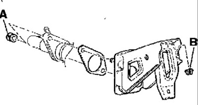
Fig. 11.8. Sequence of tightening the nuts securing the master cylinder (A) and the clutch pedal bracket (B) on vehicles with 4G93 and F9Q1 engines manufactured since 2000
- Before installation, lubricate the clutch slave cylinder push rod with grease.
- Before installation, lubricate the bushing, pin, washer and pin.
- Fill the clutch hydraulic system with brake fluid and bleed the air from it.
- Adjust the position of the clutch pedal.
[The material was copied from the website: mitsubishiman]