



Contents: Carbon filter ⤓ Float chamber vent valve (carburetor…⤓ Blow-off system ⤓ Temperature valve ⤓ Fuel tank filler cap ⤓ Safety system ⤓ Fuel control valve ⤓
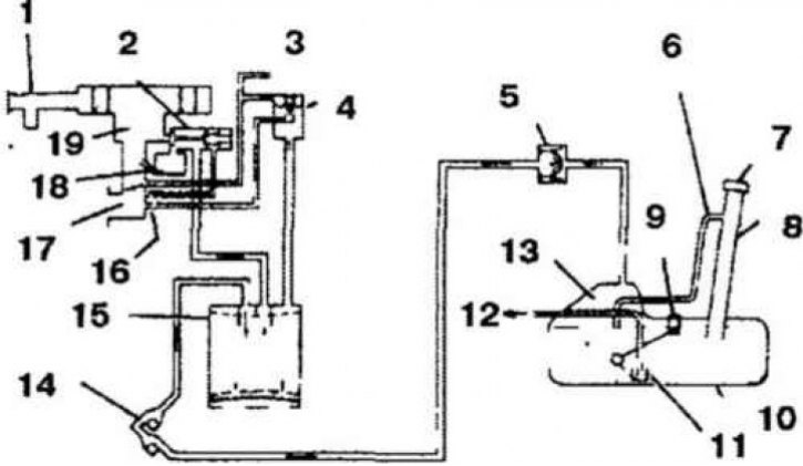
3.1a Elements of the fuel vapor collection system of models with a carburetor engine
1. Air filter; 2. Float chamber ventilation valve; 3. To temperature valve; 4. Blow-off valve; 5. Safety valves; 6. Safety system tube; 7. Filler cap; 8. Fuel filler pipe; 9. Fuel level sensor; 10. Fuel tank; 11. Filter; 12. Fuel (to the carburetor); 13. Additional volume for expansion of fuel vapors during heating; 14. Fuel control valve; 15. Carbon filter; 16. Hole; 17. Intake manifold; 18. Carburetor float chamber; 19. Carburetor
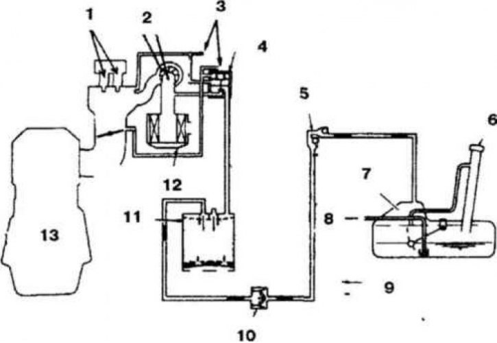
3.1b Elements of the fuel vapor collection system of models with dual-point fuel injection (TBI)
1. Injector; 2. Air intake hose; 3. To temperature valve; 4. Blow-off valve; 5. Fuel control valve; 6. Fuel tank filler cap; 7. Additional volume for expansion of fuel vapors during heating; 8. To the carburetor; 9. Fuel vapor Air; 10. Safety valves; 11. Carbon filter; 12. Air filter; 13. Engine
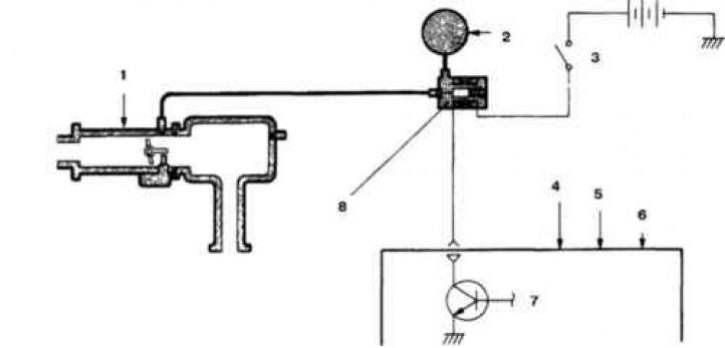
3.1c Elements of the fuel vapor collection system for models with multi-point fuel injection and an engine capacity of 1.5 l
1. Throttle body; 2. Carbon filter; 3. Control relay; 4. Incoming air temperature sensor; 5. Coolant temperature sensor; 6. Air flow sensor; 7. Electronic engine control unit; 8. Solenoid valve of the purge system
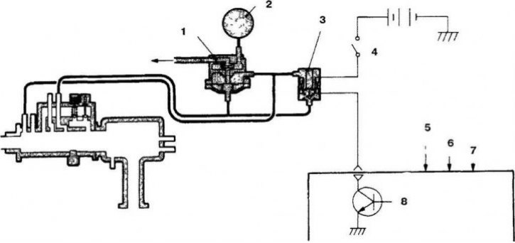
3.1g Elements of the fuel vapor collection system for models with multi-point fuel injection and an engine capacity of 1.5 l
1. Blow-off valve; 2. Carbon filter; 3. Purge solenoid; 4. Control relay; 5. Incoming air temperature sensor; 6. Coolant temperature sensor; 7. Air flow sensor; 8. Electronic engine control unit
1. The system serves to prevent fuel vapors from entering the atmosphere and consists of a carbon filter, a float chamber ventilation valve, a purge system, a safety system, a temperature valve, a fuel control valve and a special cap for the fuel tank filler neck (3.1a, 3.1b, 3.1c and 3.1g).
Carbon filter
2. When the engine is not running, fuel vapors from the fuel tank and the carburetor float chamber are collected in the carbon filter. When the engine is running, they are released into the intake manifold.
Float chamber vent valve (carburetor models)
3. The ventilation valve controls the flow of fuel vapors into the carbon filter. When the engine is running, the valve is closed, and when the engine is off, the valve is open, and the fuel vapors are collected in the carbon filter.
Blow-off system
4. The purge system is closed when the engine is idling to prevent fuel vapors from entering the intake manifold. As the engine speed increases, the purge system valve opens.
Temperature valve
5. The temperature valve monitors the coolant temperature and controls the operation of the purge system, which reduces the level of CO and HC in the exhaust gases when the engine warms up.
Fuel tank filler cap
6. The cover is equipped with a vacuum valve that prevents the release of fuel vapors into the atmosphere.
Safety system
7. The system consists of two valves:
- a) Pressure valve which opens when the internal pressure in the fuel tank exceeds the normal pressure.
- b) A vacuum valve that opens when the internal pressure in the fuel tank is below the normal level.
Fuel control valve
8. The valve prevents fuel leakage in the event of a car rollover. There are two balls installed in the valve. When the car rolls over, one of the balls closes the fuel channel, preventing fuel leakage.