



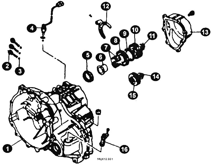
Clutch/Rear Gearbox Housing Components F5M21
1 - clutch housing; 2 - plug; 3 - ball; 4 - Reverse light switch; 5 - bearing; 6 - bearing cage; 7 - needle bearing; 8 - 5th gear pinion; 9 - synchronizer ring; 10 - synchronizer; I - lock nut; 12 - fork; 13 - back cover; 14 - lock nut; 15 - intermediate gear; 16 - speedometer drive gear.
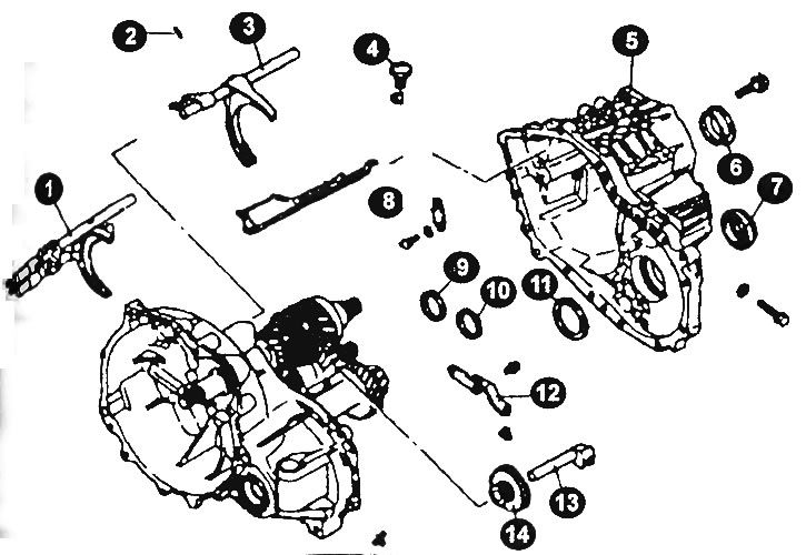
Clutch housing/transmission housing components of the F5M21 gearbox
1 - shift rod; 2 - pin; 3 - shift rod; 4 - will limit the spruce; 5 - transmission housing; 6 - outer ring; 7 - oil seal; 8 ~ Stopper bracket; 9, 10, 11 - spacer washer; 12 - reverse gear shift lever; 13 - reverse intermediate gear shaft; 14 - reverse intermediate gear.
Mount the gearbox on a suitable fixture.
Remove the back cover.
Remove the reverse light switch, gasket and ball.
Remove the flat plug, spring and ball.
Remove the speedometer drive gear assembly and breather.
Remove the elastic pin.
Remove the pin using a punch.
Remove the cotter pins from the input shaft and intermediate shaft lock nuts.
Engage the reverse gear of the main gear using the control levers.
Install the mandrel on the primary shaft.
Screw a 10mm bolt into the hole on the surface of the clutch housing and attach the handwheel handle to the mandrel to remove the lock nut.
Remove the 5th gear synchronizer sleeve and shift sleeve.
Remove the 5th gear synchronizer hub, 5th gear synchronizer ring, needle bearing, bearing sleeve and roller bearing.
After removing the spring ring, remove the spacer and roller bearing.
Remove the intermediate gear.
Remove the reverse intermediate gear shaft bolt and gasket.
Disconnect the final drive housing from the clutch housing.
Remove the differential seal and guide.
Remove the bolt, spring washer and stopper bracket.
Remove the stop ball assembly, gasket and seal.
Remove the 3 outer bearing races and spacers.
Remove the bolt and reverse gear shift lever assembly, shift lever shoe, idler gear shaft and idler gear.
Remove the shift pins, shift rods and shift forks (1) and (2) (see figure).
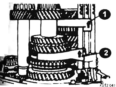
Remove the two bolts and the bearing holder.
Raise the input shaft assembly and remove the intermediate shaft assembly.
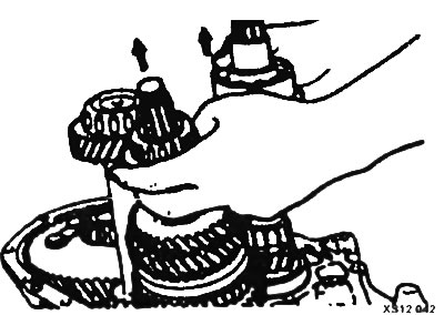
Remove the primary shaft assembly and secondary shaft assembly.
Remove the differential drive gear assembly.
Remove 3 bearing rings and guide ring.
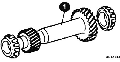
Secondary shaft elements (1)
Remove the two oil seals, magnet and magnet holder.