
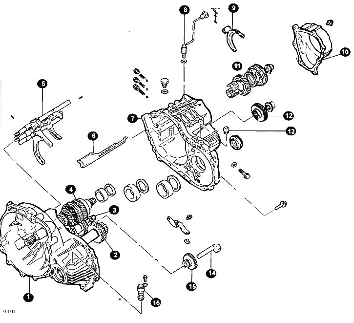
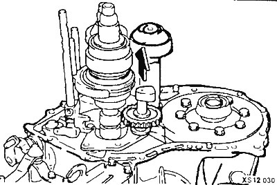
F5M22 gearbox clutch housing elements
1 - clutch housing; 2 - secondary shaft; 3 - intermediate shaft; 4 - input shaft; 3 - shift forks; 6 - oil tray; 7 - gearbox housing; 8 - reverse lamp switch; 9 - 5th gear engagement fork; 10 - back cover; 11 - gear wheel of the 5th gear; 12 - intermediate gear; 13 - breather; 14 - axis of the parasitic reverse gear; 15 - parasitic reverse gear; 16 - speedometer drive gear.
Mount the gearbox on a suitable bench or workbench.
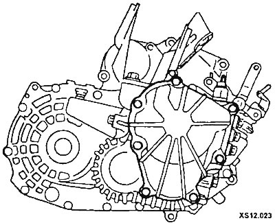
Remove the back cover.
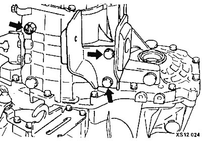
Remove the reversing lamp switch, gasket and bracket.
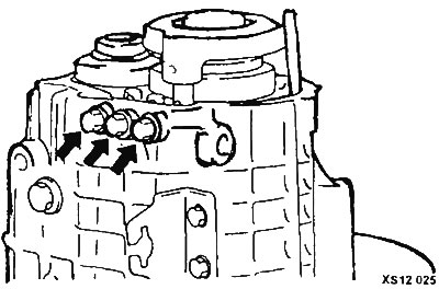
Unscrew the plugs (arrow) remove springs and balls (arrow in fig. XS12.025).
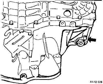
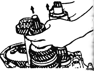
Remove the speedometer drive gear assembly (arrow) and breather (pic. XS12.026).
Remove the pin with a punch.
Loosen the lock nuts on the input shaft and intermediate shaft.
Engage reverse gear with the control levers.
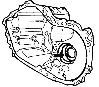
Install the mandrel on the input shaft. Screw a 10mm bolt into the hole on the side of the clutch housing and attach the handwheel handle to the arbor to remove the lock nut.
Remove the reverse idler shaft bolt and remove the gasket.
Disconnect the final drive housing from the clutch housing.
Remove the differential seal and guide.
After unscrewing the bolt, remove the spring washer and stopper bracket.
Remove the stop ball gasket and seal assembly.
Remove the 3 outer bearing races and spacers.
After removing the bolt, remove the reverse shift lever assembly, shift lever shoe.
Remove the idler shaft and idler gear.
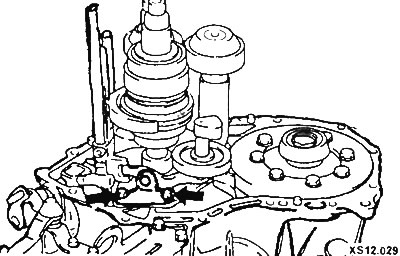
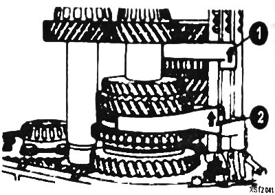
Remove shifter pins, shifter rods and forks (1, 2).
After unscrewing the two bolts, remove the bearing holder.
Raise the input shaft assembly and remove the intermediate shaft assembly.
Remove the input shaft assembly and output shaft assembly.
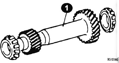
Elements of the output shaft (1)
Remove the differential drive gear assembly.
Remove 3 bearing rings and guide ring.
Remove the two oil seal magnet and magnet holder.
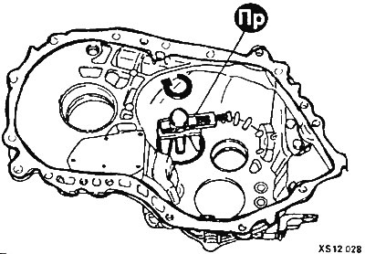
Remove the controls from the clutch housing according to drawing XS12.039).
ATTENTION: Remove the controls in case of emergency, because. the disassembly process is about cutting the locking plate (4). When assembling, you will need a new locking plate.
Disassemble, wash and check the gearbox elements.
Check the stems and forks for wear and damage. Replace if necessary (pic. XS12.036).
The gearbox is assembled in the reverse order.
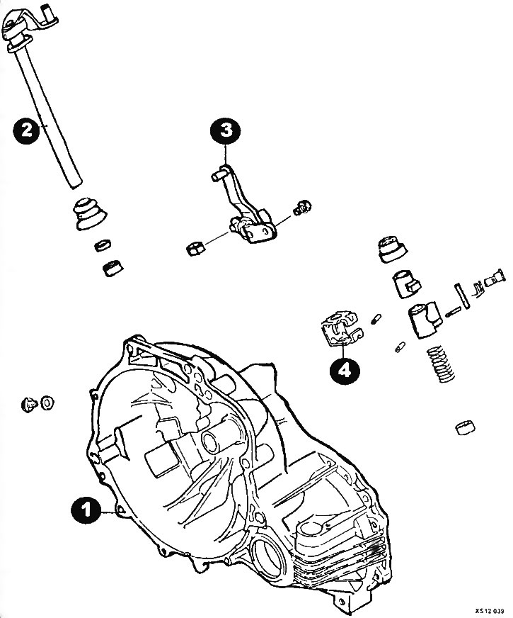
Controls
1 - clutch housing; 2 - control fork; 3 - gear selection lever; 4 - locking plate.
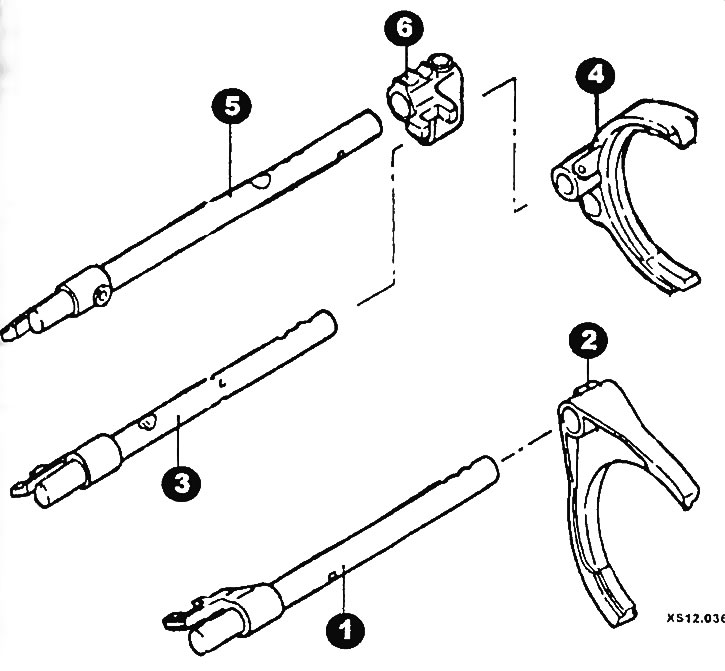
F5M22 transmission rods and yoke
1 - shift rod 1st - 2nd gear; 2 - fork; 3 - shift rod 3rd - 4th gear; 4 - fork; 5 - 5th gear engagement rod; 6 - clip.