



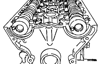
Figure 3.34a. Correct location of camshaft pins when installing camshaft main bearing caps
2. Main bearing caps No.2 and No.5 are of the same shape (Figure 3.34b). Install them in numerical order and check the identification marks to avoid mixing up the inlet and outlet side caps.
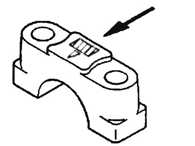
Figure 3.346. Location of the number and identification mark of main bearing caps No.2 and No.5
Identification marks: I - inlet side, E - outlet side.
(The text of the article was taken from the website: «MITSUBISHIMAN»)
3. Apply 3M ATD #8660 or equivalent sealant to the cylinder head surface. Then tighten the inner main bearing cap bolts first, then the outer ones. Tighten the bolts evenly and in several stages until the required tightening torque is reached (Figure 3.35). Make sure the rocker arms are installed correctly.
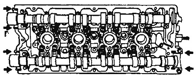
Figure 3.35. Main bearing cap bolt tightening sequence