



2. Adjust the valves shown in Figure 3.39a, b. To do this, loosen the lock nut of the adjusting screw, install the measuring gauge and adjust the valve clearance by turning the adjusting bolt (Figure 3.40). Hold the adjusting bolt with a screwdriver and tighten the lock nut.
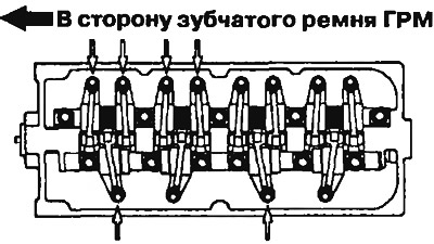
Figure 3.39a. Valve clearance adjustment procedure on 12V SOHC engines | 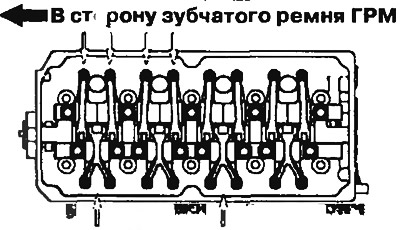
Figure 3.39b. Procedure for adjusting the thermal clearance of valves on SOHC 16V engines |
Thermal clearance on a cold engine: intake valve - 0.09 mm, exhaust valve - 0.17 mm.
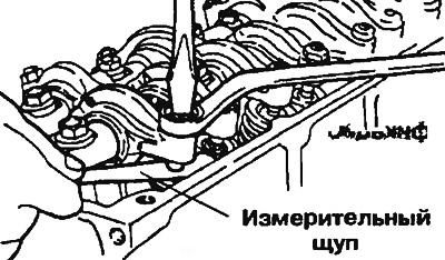
Figure 3.40. Adjusting the valve clearance
3. Rotate the crankshaft one revolution (360°) clockwise.
4. Adjust the valves shown in Figure 3.41a,b. Repeat the steps in step 2 to adjust the clearance in the valves indicated above.
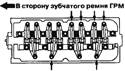
Figure 3.41a. The procedure for adjusting the thermal clearance of the remaining valves on SOHC 12V engines | 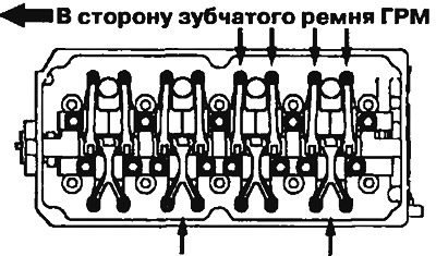
Figure 3.41b. The procedure for adjusting the thermal clearance of the remaining valves on SOHC 12V engines |
(The text of the article was obtained from the website www.MitsubishiMan.ru)
5. If the engine is installed on the car, start it. After that, check the valve clearance on a warm engine and, if necessary, adjust it.
Thermal clearance on a warm engine: inlet valve - 0.20 mm, outlet valve - 0.25 mm.