2. Disconnect the control unit connector. The engine control unit from the wiring side is shown in fig. 8.3.
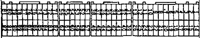
Pic. 8.3. Engine control unit on the wiring side
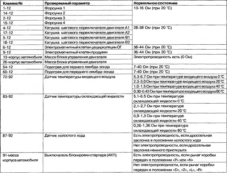
3. Measure the resistance and, according to Table 8.6, check for continuity between the control unit terminals on the wiring side.
Attention! The verification process does not have to be carried out in the sequence given in the table. Observe the connection and grounding of the terminals, otherwise all devices may fail.
4. If the ohmmeter shows deviations from the normal values, check the appropriate sensor, its connection and wiring. Repair or replace if necessary.
5. After repair or replacement, check with an ohmmeter whether the faults in the indication of values have been eliminated.
Table 8.6. Table for checking resistance and electrical conductivity between terminals