
Examination
1. Disconnect the connector from the throttle position sensor (pic. 8.20a).
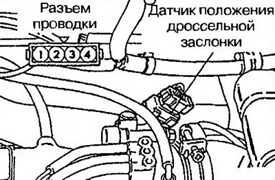
Pic. 8.20a. Disconnect the connector from the throttle position sensor
2. Measure the resistance between terminals 1 and 4 of the sensor. Normal value: 3.5-6.5 kOhm.
3. Measure the resistance between terminals 2 and 4. Slowly open the throttle from idle to «full throttle» - the resistance should decrease in direct proportion to the throttle opening.
4. If the measured value does not correspond to the specified value or does not change proportionally and uniformly, replace the throttle position sensor.
Installation
5. Install the throttle position sensor as shown in fig. 8.20b, and tighten the mounting bolts.
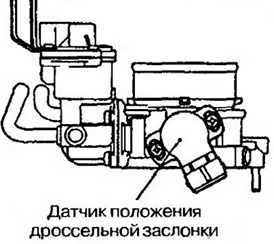
Pic. 8.206. Install the throttle position sensor and tighten the mounting bolts
6. Connect a diagnostic tool between terminal 1 (power supply) and terminal 2 (exit) connector and check that the resistance increases gradually while slowly opening the throttle until «full throttle» (pic. 8.20v).
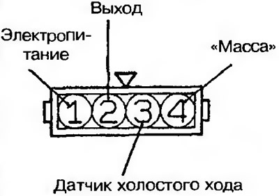
Pic. 8.20th century Resistance test between throttle position sensor connector terminals
7. Check sensor wiring connector for continuity between terminal 3 (idle sensor) and terminal 4 («weight»), when the damper is fully open and fully closed.
Normal condition:
| Throttle position | Electrical conductivity |
| Completely closed | Yes |
| Fully open | No |
If there is no continuity at full throttle, turn the throttle position sensor housing counterclockwise and check again.
8. If a defect is found, replace the sensor.