
Disassembly
1. Removal of the ball bearing is shown in fig. 11.84, removal of the plug of a brake cone of transfer of a backing - on fig. 11.85, removal of the synchronizer hub for 5th gear / reverse gear - in fig. 11.86, removal of the plug of a gear wheel of 5th transfer - on fig. 11.87, removal of the plug of a gear wheel of 4th transfer - on fig. 11.88. removal of the ball bearing - in fig. 11.89.

Pic. 11.84. Removing the ball bearing | 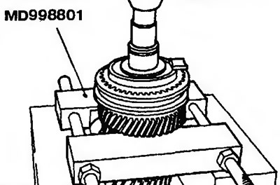
Pic. 11.85. Removal of the bushing of a brake cone of transfer of a backing |
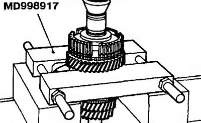
Pic. 11.86. Removing the Synchronizer Hub for 5th/Reverse Gear | 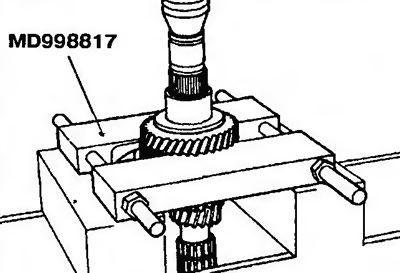
Pic. 11.87. Removing the 5th gear bushing |
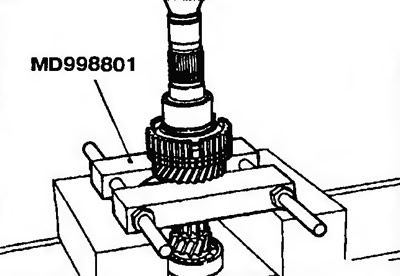
Pic. 11.88. Removing the 4th gear bushing | 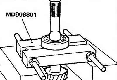
Pic. 11.89. Removing the ball bearing |
Assembly
Snap ring
2. Select and install the circlip so that the input shaft front bearing end play is correct (pic. 11.91). Required clearance: - 0.01 to 0.12 mm.
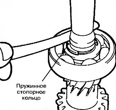
Pic. 11.90. Checking the axial clearance of the input shaft front bearing
Synchronizer hub 3rd and 4th gears
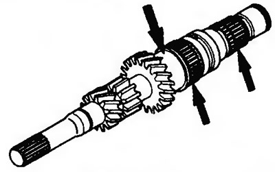
3. Install the 3rd and 4th gear synchronizer hub (pic. 11.91). When installing the hub, make sure that the synchronizer ring is not pinched (pic. 11.92).
Pic. 11.91. Install the 3rd and 4th gear synchronizer hub | 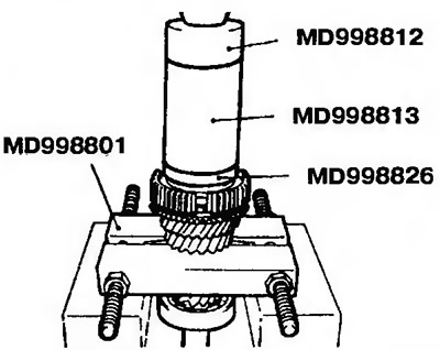
Pic. 11.92. When installing the hub, make sure that the synchronizer ring is not pinched |
Synchronizer clutch
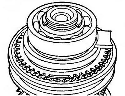
4. Install the synchronizer clutch (pic. 11.93).
Pic. 11.93. Install the synchronizer clutch
5. When installing the synchronizer clutch, the deep part of the groove on the synchronizer hub must be aligned with the protruding part of the clutch (pic. 11.94).
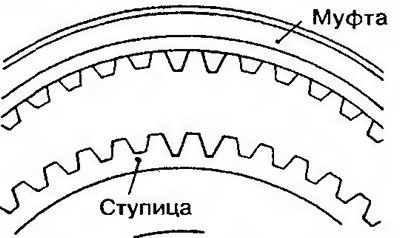
Pic. 11.94. When installing the synchronizer clutch, the deep part of the groove on the synchronizer hub must be aligned with the protruding part of the clutch
Snap ring
6. Select and install a circlip such that the input shaft front bearing axial clearance will correspond to the required (fig.11.95). Required clearance: - 0.01 to 0.09 mm.
Pic. 11.95. Installation of a snap ring and check of an axial backlash of the forward bearing of an input shaft
Examination
Input shaft
7. Check the outer surface under the needle bearing for damage, excessive wear and corrosion. Check splines for damage and wear (pic. 11.96).
Pic. 11.96. Check the outer surface under the needle bearing for damage, excessive wear and corrosion. Check splines for damage and wear
Synchronizer blocking ring
8. Check for damage or breaks in the toothed surface of the clutch gear. Make sure that the inner part of the cone and the threaded part are not damaged or worn (pic. 11.97).
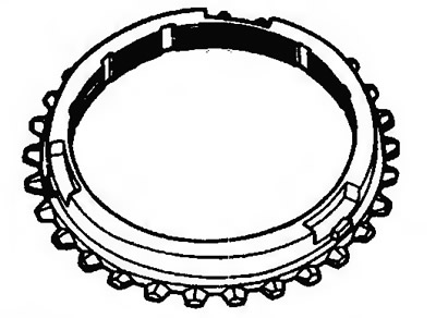
Pic. 11.97. Check for damage or breakage of the gear surface of the clutch gear
9. Press the synchronizer blocking ring against the gear and check clearance A (pic. 11.98). Replace the part if the measured gap exceeds the allowable. Permissible gap: 0.5 mm.
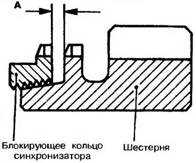
Pic. 11.98. Press the synchronizer ring against the gear and check gap A