



Removal
1. Release the pressure in the system (see section 2).
2. Disconnect the cable from the negative battery terminal.
3. Drain the coolant to the intake manifold level or below.
4. Disconnect the water supply hose (connected between the jet mixer and the inlet manifold) from the jet mixer pipe.
5. Disconnect the air intake tube from the jet mixer.
6. Disconnect the cable from the jet mixer throttle control lever.
7. Clearly mark and then disconnect the vacuum hoses from the jet mixer nozzles.
8. Disconnect the electrical wiring connectors from the injectors.
9. Disconnect the wiring connectors from the ISC and TPS servo.
10. Disconnect the fuel supply pipe and fuel return hose from the jet mixer.
Warning: Although the fuel pressure has been released, loosen the two bolts securing the fuel supply pipe and disconnect the hose carefully, gradually relieving the residual pressure. If the fuel pipe is disconnected abruptly, the residual pressure may cause fuel to be ejected.
11. Mark the position of the throttle position sensor relative to the mounting element. Remove the throttle position sensor.
12. Disconnect the rubber hose connecting the fuel pressure regulator to the mixer body.
13. Unscrew the screws securing the injector holder and remove the holder (see illustration).
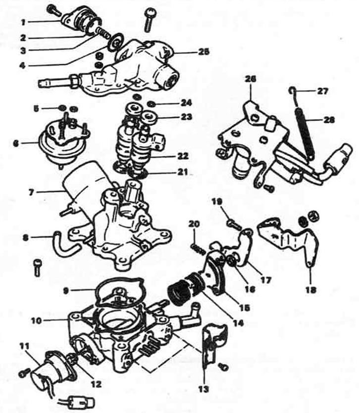
13.13 Exploded view of the jet mixer unit. 1. Pulsation damper cover, 2. O-ring, 3. Spring, 4. Pulsation damper, 5. O-ring, 6. Fuel pressure regulator, 7. Mixer body, 8. Hose, 9. O-ring, 10. Throttle body, 11. Throttle position sensor, 12. Coupling, 13. Connector bracket, 14. Return spring, 15. Throttle lever, 16. Ring, 17. Free lever, 18. Throttle release lever, 19. Adjusting screw, 20. Spring, 21. O-rings (2), 22. Injectors, 23. Bushings, 24. O-rings (2), 25. Holder injectors, 26. ISC servo, 27. Damper spring, 28. Return spring
14. Remove the fuel pressure regulator from the holder.
15. Remove the pulsation damper cover from the holder, then remove the spring with the diaphragm.
16. Remove the nozzles from the mixer body. Do not try to remove the nozzles with pliers - you can damage them. Remove the nozzle gasket from the body.
17. Remove the throttle return spring and damper spring.
18. Remove the connector bracket.
19. Remove the ISC servo bracket mounting bolts and remove the ISC servo and bracket.
20. Unscrew the two screws and remove the mixer body with the sealing ring from the throttle body.
Bulkhead
21. With the exception of the throttle position sensor and ISC servo, wash all parts in solvent. Submerging the TPS or ISC servo in solvent will damage their insulation. Instead, wipe them with a clean rag. Before cleaning the injectors and fuel pressure regulator in solvent, plug the fuel inlet and outlet pipes with Teflon tape. Check all vacuum fittings and fuel passages for blockage. Clean them with compressed air.
Installation
22. Install a new O-ring into the groove of the throttle body.
23. Install the mixer body onto the throttle body and tighten the mounting screws securely.
24. Install the ISC servo with the bracket and tighten the mounting screws securely.
25. Install the connector bracket to the throttle body and insert the ISC connector into the bracket.
26. Install the throttle return spring and damper spring.
27. Install new sealing rings into the mixer body. When installing the sealing rings, insert them with the flat surface facing up (see illustration).
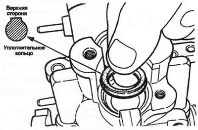
13.27. Check the correct installation of the injector sealing rings.
28. Install new sealing rings on the injectors.
29. Install the nozzles into the mixer body. Insert the nozzles manually until they stop. If you are replacing the nozzle(s) with new ones, please note that each nozzle has a designation stamped on the body. Check that the designation on the new nozzle matches the designation on the old one.
30. Insert the pulsation damper diaphragm into the injector holder.
31. Replace the pulsation damper spring and cover, then tighten the screws.
32. Install new O-rings on the pulsation damper, then insert the regulator into the injector holder.
33. Check the patency and integrity of the filters in the holder. Replace if necessary.
34. Replace the nozzle holder and press firmly. Then tighten the screws evenly.
35. Using the marks made during disassembly, reinstall the throttle position sensor onto the throttle body (see illustration).
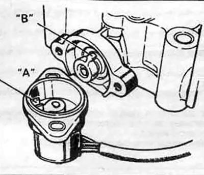
13.35. When installing the TPS sensor, check that petal "B" fits into slot "A"
36. Clean both sealing surfaces of the jet mixer and the inlet manifold.
37. Install the new jet mixer gasket onto the intake manifold.
38. Install the jet mixer assembly onto the intake manifold and tighten the mounting bolts.
39. Install a new sealing ring into the groove of the high-pressure hose and connect the high-pressure hose to the jet mixer. Tighten the hose mounting bolts securely.
40. Connect the fuel supply hose to the fuel pressure regulator fitting.
41. Connect all electrical connectors to the injectors, ISC servo and sensors.
42. Insert the throttle position sensor connector into its bracket.
43. Connect the vacuum hoses to the corresponding nozzles of the jet mixer.
44. Connect the water supply hose to the nozzle of the jet mixer.
45. Install the air supply tube.
46. Fill the cooling system.
47. Connect the wire to the negative battery terminal.
48. Check that the throttle position sensor is installed correctly. Measure the resistance between terminals 1 and 2 or 2 and 3 while moving the throttle lever from the open position to the closed position (see illustration). If the resistance changes, the throttle position sensor is installed correctly.
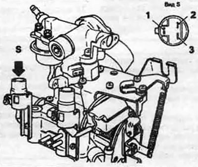
13.48 Connect an ohmmeter between terminals 1 and 2 or 2 and 3 of the TPS connector to check for a change in resistance as the throttle valve opens.
49. Start the engine and warm it up to normal operating temperature.
50. With the engine running, check for oil and coolant leaks.
51. The throttle position sensor adjustment should be checked. This check and, if necessary, adjustment should be performed by a specialist.