



Contents: Removal ⤓ Installation ⤓
Removal
1. Disconnect the cable from the negative terminal of the battery.
2. Remove the hood.
3. Drain the coolant from the engine cooling system.
4. Remove the air filter.
5. Remove the radiator.
6. Remove the intercooler air duct.
7. Remove the exhaust inlet pipe.
8. Remove the accessory drive belt.
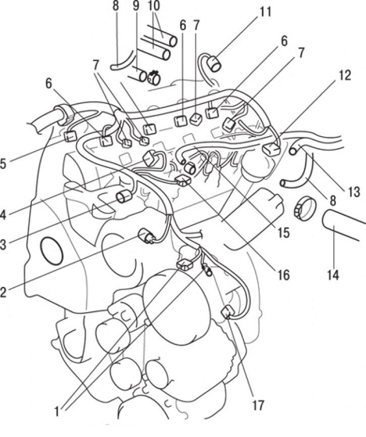
Fig. 5.24. Connecting connectors and hoses to the F9Q engine: 1 – generator connectors; 2 – pressure sensor connector; 3 – fuel pump connector; 4 – pressure sensor connector; 5 – camshaft position sensor connector; 6 – fuel injector connector; 7 – glow plug connector; 8 – connection of vacuum hoses; 9 – brake booster hose connection; 10 – heater hose connections; 11 – EGR valve connector; 12 – coolant temperature sensor connector; 13 – connection of the return fuel hose; 14 – connection of the upper radiator hose; 15 – fuel supply hose connection; 16 – Engine temperature sensor connector; 17 – Air conditioning compressor connector
9. Disconnect the connectors of the camshaft position sensor 5 (Fig. 5.24), pressure sensor 4, fuel pump 3, engine temperature sensor 16, fuel injector 6, glow plug 7, coolant temperature sensor 12, EGR valve 11, air conditioning compressor 17, generator 1 and pressure sensor 2.
10. Disconnect the vacuum hoses 8.
11. Loosen the clamp and remove the brake booster hose 9.
12. Loosen the clamp and remove the upper radiator hose 14.
13. Loosen the clamps and remove the heater hoses 10.
14. Loosen the clamp and remove the return fuel hose 13.
15. Loosen the clamp and remove the fuel supply hose 15.
16. Loosen the bolts and remove the power steering pump from the bracket together with the hoses connected to it.
Caution! Tie the removed power steering pump with wire and place it in a place where it will not interfere with the removal and installation of the engine assembly.
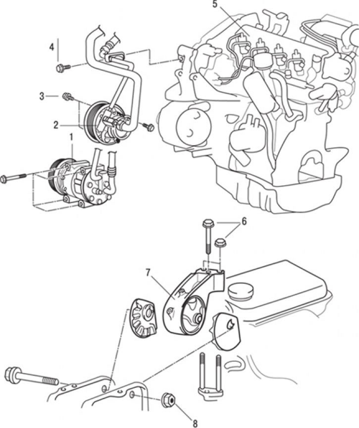
Fig. 5.25. F9Q engine: 1 – air conditioning compressor; 2 – Power steering pump; 3 – bolt, 60 Nm; 4 – bolt, 10 Nm; 5 – engine; 6 – bolt, 54 Nm; 7 – Engine support bracket; 8 – bolt, 90 Nm
17. Disconnect the air conditioning compressor wire connector and remove compressor 1 (Fig. 5.25) from its bracket together with the connected hoses.
Caution! Tie the removed compressor with wire and place it in a place where it will not interfere with the removal and installation of the engine.
18. Place a hydraulic jack under the engine.
19. Remove the special tool used to remove the gearbox from the engine.
20. Secure the engine to the crossbar and suspend it from a hoist or similar device.
21. Insert a wooden block between the jack support foot and the engine oil pan and lift the engine slightly to relieve the support; then remove the engine mount bracket.
22. Check that all wires (electrical connectors), hoses, etc. are disconnected from the engine, and then slowly lift the engine out of the engine compartment.
Installation
Installation is carried out in the reverse order of removal, taking into account the following.
1. When installing the engine, carefully check that the wires, hoses and wire connectors are not pinched.
2. Place a hydraulic trolley jack under the engine (inserting a wooden block between the jack support foot and the engine oil pan) and install the engine support bracket, adjusting the engine position using the jack.
3. Support the engine with a jack.
4. Support the engine with a jack and disconnect the hoist.
5. Finally, install the exhaust pipe.
6. Install the radiator.
7. Install the gearbox.
8. Fill the cooling system with coolant.
9. Adjust the drive belt tension.
10. Install the intercooler duct.
11. Install the inlet hose and air filter.
12. Remove air from the fuel line.
13. Install the hood.
14. With the engine installed in the engine bay of the vehicle, check the engine oil and coolant levels. Check that all previously removed wires and hoses are in place.