
Removing
1. Drain the coolant from the engine cooling system.
2. Drain the engine oil from the engine.
3. Remove the intake hose and air filter.
4. Remove the downpipe and catalytic converter.
5. Remove the toothed belt.
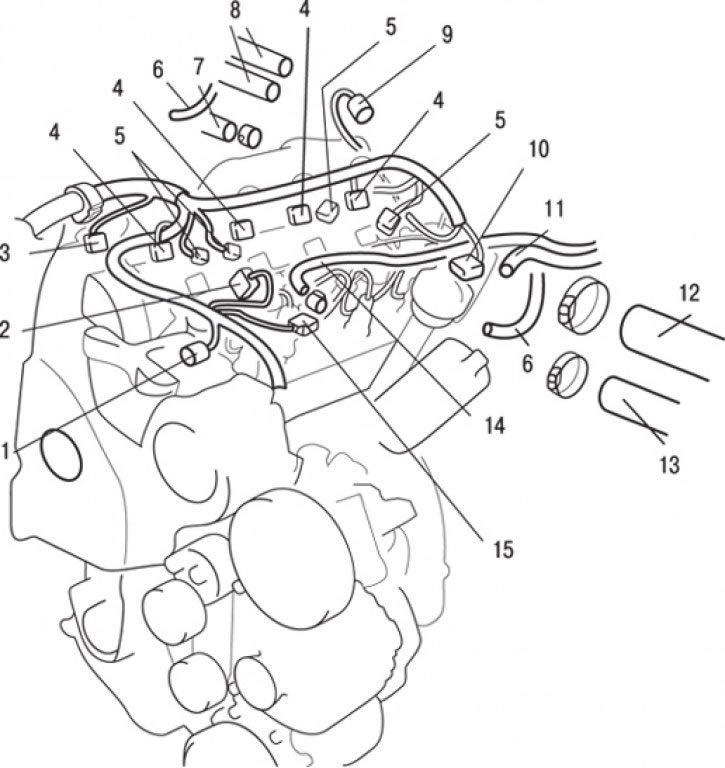
Pic. 5.11. Connecting connectors and hoses to the cylinder head of the F9Q engine: 1 – a socket of the fuel pump; 2 - pressure sensor connector; 3 – a socket of the gauge of provision of a camshaft; 4 - fuel injector connector; 5 - glow plug connector; 6 – connection of vacuum hoses; 7 – connection of a hose of the vacuum amplifier of brakes; 8 – connections of heater hoses; 9 - EGR valve connector; 10 – a socket of the gauge of temperature of a cooling liquid; 11 - connection of the return fuel hose; 12 – connection of the top hose of a radiator; 13 – connection of a hose of system of cooling; 14 - connection of the supply fuel hose; 15 – a socket of the gauge of temperature of the engine
6. Disconnect the camshaft position sensor connectors 3 (pic. 5.11), pressure sensor 2, fuel pump 1, engine temperature sensor 15, fuel injector 4, glow plug 5, coolant temperature sensor 10 and EGR valve 9.
7. Disconnect the vacuum hoses 6.
8. Loosen the clamp and disconnect the hose 7 of the vacuum brake booster.
9. Loosen the clamp and disconnect the upper hose 12 of the radiator.
10. Loosen the clamp and disconnect the hose 13 of the cooling system.
11. Loosen the clamps and disconnect the heater hoses 8.
12. Disconnect the fuel return hose 11.
13. Disconnect the supply fuel hose 14.
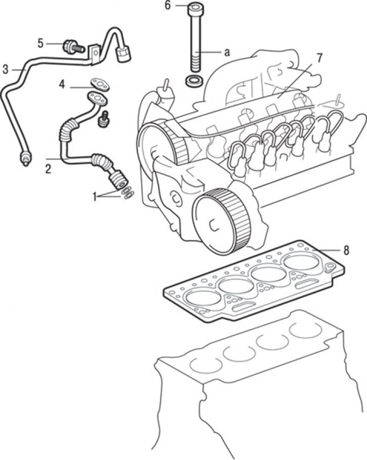
Pic. 5.12. Cylinder Head Gasket: a - place of lubrication; 1 - sealing rings; 2 - a tube of a return oil pipeline; 3 – oil pipeline tube; 4 - gasket; 5 - bolt, 10 Nm; 6 – cylinder head mounting bolt, 30 Nm + 100°±4°+ 0 Nm + 25 Nm + 213°±7°; 7 – cylinder head; 8 – a lining of a head of the block of cylinders
14. Unscrew and disconnect tube 3 (pic. 5.12) oil pipeline.
15. Unscrew and disconnect tube 2 of the oil return line.
16. Remove gasket 4.
17. Remove sealing rings 1.
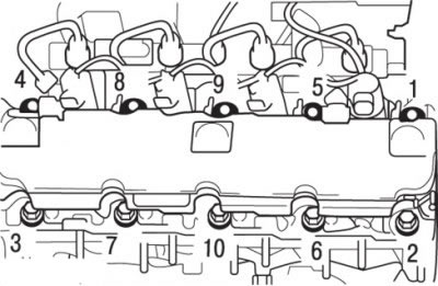
Pic. 5.13. The sequence of turning out the bolts of the cylinder head
18. Turn out bolts of fastening of a head of the block of cylinders in 2 or 3 stages in the sequence resulted in fig. 5.13, then remove the cylinder head assembly.
19. Being careful, remove a head of the block of cylinders in gathering.
20. Remove the cylinder head gasket.
Preparing for installation
1. The mating surfaces of the head and cylinder block must be completely clean. Use a hard plastic or wooden scraper to clean them. Be careful when cleaning as aluminum alloy is very easy to damage. Check that carbon deposits do not get into the oil and water channels. This is especially important for the lubrication system, since deposits can block the oil supply to engine components. Clean channels if necessary.
4. Clean the bolt holes in the block. Screwing a bolt into an oil-filled hole may rupture the block due to hydraulic pressure.
Installation
Installation is carried out in the reverse order of removal, taking into account the following.
1. Degrease mating surfaces of the gasket.
2. Install the cylinder head gasket and check that all holes in the gasket and cylinder block match.
3. Use only new bolts of fastening of a head of the block of cylinders.
4. Before installing the bolts and washers, lubricate the threaded parts of the bolts and the surfaces of the washers with a small amount of engine oil.
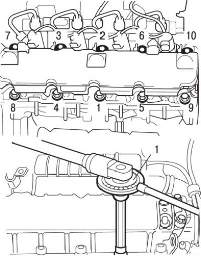
Pic. 5.14. The sequence of tightening the cylinder head bolts: 1 - MB991614 key for screwing bolts to the required angle
5. Tighten bolts of fastening of a head of the block of cylinders in several stages in the sequence shown in fig. 5.14.
Bolt tightening steps:
- 1st - tighten with a torque of 30 N·m;
- 2nd - tighten by an angle of 100°± 4°;
- 3rd - wait at least 3 minutes;
- 4th - loosen bolts 1 and 2;
- 5th - tighten bolts 1 and 2 to 25 Nm;
- 6th - tighten the bolts at an angle of 213°± 7°;
- 7th - divide the remaining bolts into pairs 3 and 4, 5 and 6, 7 and 8, 9 and 10 and tighten them in pairs according to steps 3, 4 and 5.