



Contents: Removal ⤓ Installation ⤓
Removal
1. Disconnect the cable from the negative terminal of the battery.
2. Remove the engine mount bracket.
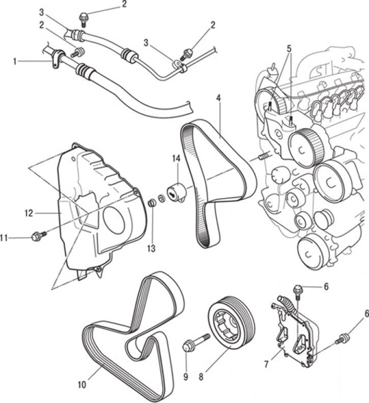
Fig. 5.15. Timing belt of the gas distribution mechanism: 1 – air conditioner suction hose; 2 – bolt, 10 Nm; 3 – connection of the power steering pressure hose; 4 – toothed drive belt; 5 – hairpins; 6 – bolt, 25 Nm; 7 – Engine Control Unit ECU; 8 – crankshaft pulley; 9 – bolt, 20 Nm + 115° ±15°;10 – belt; 11 – bolt, 9 Nm; 12 – timing belt cover; 13 – bolt, 50 Nm; 14 – Timing belt tensioner pulley
3. Loosen the bolt and remove the suction hose 1 (Fig. 5.15) of the air conditioner.
4. Loosen the bolts and remove the power steering pressure hose 3.
5. Loosen the bolts, remove the engine control unit ECU 7 and, without disconnecting the wiring harness from it, move it to the side.
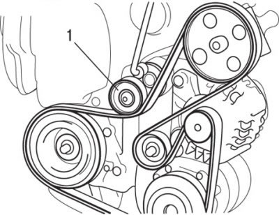
Fig. 5.16. Reducing the belt tension by turning the automatic tensioner mechanism (1) of the belt pulley clockwise using a 16 mm wrench
6. Place a 16mm wrench on the lug of the automatic belt pulley tensioner, turn the belt pulley tensioner clockwise and remove the belt (Fig. 5.16).
Caution! The belt used to remove the pulley will be damaged. Do not use the standard engine accessory drive belt (use another belt).
Never install a damaged belt on an engine.
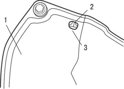
Fig. 5.17. Alignment of the timing mark of the camshaft pulley with the center of the toothed belt cover window: 1 – timing belt cover; 2 – installation mark; 3 – window
7. Turn the crankshaft clockwise so that the piston of the 1st cylinder (from the flywheel side) moves to TDC, while the timing mark of the camshaft pulley should be aligned with the center of the window of the toothed belt cover (Fig. 5.17).
8. Holding the pulley from turning with a special tool, unscrew the bolts and remove the crankshaft pulley.
9. Unscrew studs 5 (see Fig. 5.15).
10. Unscrew the bolts and remove the 12 tooth belt cover.
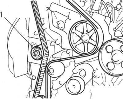
Fig. 5.18. Location of the nut (1) for fastening the toothed belt tensioner pulley
11. Loosen the nut securing the toothed belt tensioner pulley, loosen the belt tension and remove it (Fig. 5.18).
Caution: Only a new timing belt must be used during installation.
Installation
Installation is carried out in the reverse order of removal, taking into account the following.
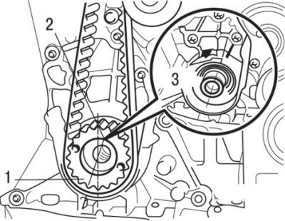
Fig. 5.19. Position of the toothed belt on the engine crankshaft pulley: 1 – crankshaft groove; 2 – installation mark; 3 – ribs
1. Turn the crankshaft clockwise to align the crankshaft groove with the center of the two ribs of the crankshaft housing. Also, check that the timing mark of the crankshaft pulley is offset by a tooth to the left of the perpendicular position of the engine crankshaft (Fig. 5.19).
2. Check that the timing mark on the camshaft pulley is aligned with the center of the timing belt cover window.
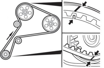
Fig. 5.20. Alignment of marks with pointers on the crankshaft and camshaft pulley
3. Install the timing belt so that the lines on the belt align with the indicators on the crankshaft and camshaft pulley (Fig. 5.20).
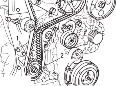
Fig. 5.21. Fastening the crankshaft pulley with washer No.4 of special tool MB996048: 1 – special tool MB996048; 2 – crankshaft pulley mounting bolt
4. Install washer No.4 of special tool MB996048 and secure the crankshaft pulley to the crankshaft with a bolt (Fig. 5.21).
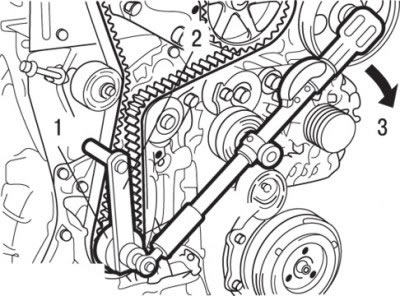
Fig. 5.22. Timing belt tension: 1, 2 – special tool MB996048; 3 – tension torque 11 Nm
5. Install cover No.1 of special tool MB996048 onto the crankshaft pulley mounting bolt and use a torque wrench to tighten the timing belt to 11 N·m (Fig. 5.22).
6. Remove special tool MB996048 and special tool cover No.1 MB996048.
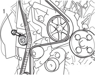
Fig. 5.23. Location of bolt (1) in the toothed belt tensioner pulley
7. Screw the bolt into the toothed belt tensioner pulley and tighten the bolt so that the belt tension does not change (Fig. 5.23).
8. Check the timing belt tension and readjust if necessary.
9. Secure the crankshaft pulley from turning as when removing it, tighten the pulley mounting bolt to a torque of 20 N·m and then turn it further by an angle of 115° ±15°.