



2. Loosen the adjusting nut securing the cable to the control lever.
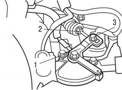
Fig. 12.7. Adjusting the selector switch and selector cable: 1 – manual control lever; 2 – selector cable; 3 – nut
3. Set the manual control lever to the "N" position (see Fig. 12.7).
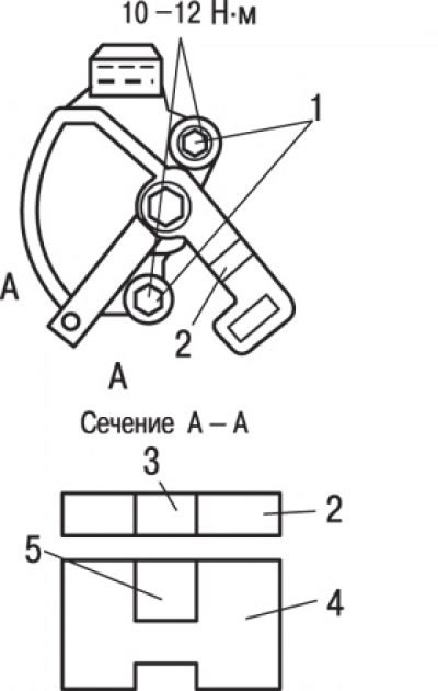
Fig. 12.8. Alignment of the hole in the flange of the switch housing with the hole at the end of the manual control lever during adjustment: 1 – bolts; 2 – manual control lever; 3 – hole at the end of the lever; 4 – selector switch housing; 5 – hole in the housing flange
4. Loosen the selector switch mounting bolts and turn it so that the hole in the switch housing flange aligns with the hole at the end of the manual control lever (Fig. 12.8, section A–A).
5. While holding the switch in this position, tighten its mounting bolts.
6. Carefully pull the cable connecting the selector lever to the control valve block in the direction of the arrow (see Fig. 12.7) and then tighten the adjusting nut to a torque of 12 N·m.
7. Make sure the selector lever is in the "N" position.
8. Check that the gears to be engaged correspond to the position of the selector lever.
The article was taken from the website: MitsubishiMan.ru