



Contents: Removal ⤓ Installation ⤓
Removal
- Remove the floor console.
- Remove the cotter pin, remove the washer and disconnect the gearbox control cable end from the lever on the gearbox (Fig. 13.36).
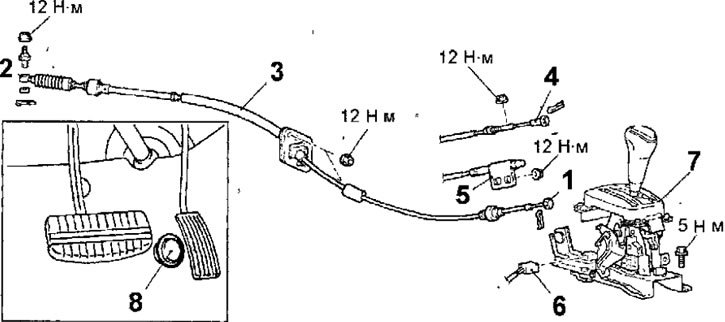
Fig. 13.36. Gearbox control cable: 1 - gearbox control cable end (selector lever side); 2 - gearbox control cable tip (gearbox side); 3 - gearbox control cable; 4 - ignition switch lock cable tip; 5 - selector lever lock cable tip; 6 - connector for selector lever position indicator lamp; 7 - selector lever; 8 - Full throttle open switch
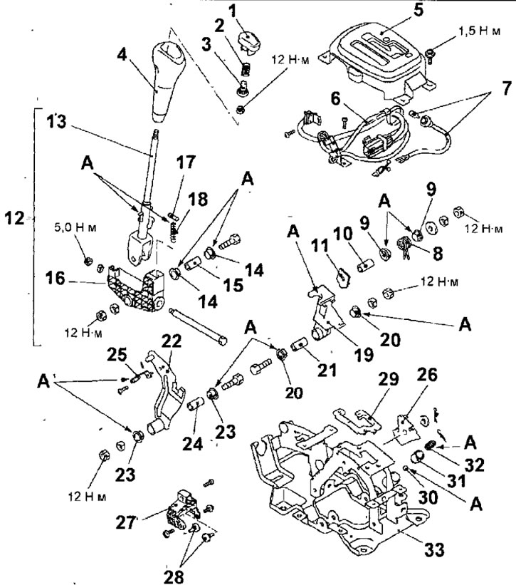
Fig. 13.37. Selector lever: A - lubrication points with universal consistent grease; 1 - button; 2 - spring; 3 - regulator; 4 - handle; 5 - indicator panel assembly; 6 - locking switch; 7 - indicator lamp; 8 - return spring; 9 - bushing; 10 - pipe; 11 - bracket; 12 - selector lever; 13 - lever; 14 - insert; 15 - bushing; 16 - lever; 17 - pin; 18 - spring; 19 - hand lever; 20 - insert; 21 - bushing; 22 - cable lever; 23 - insert; 24 - bushing; 25 - retainer spring; 26 - cam of the locking mechanism; 27 - guide block; 28 - rubber stopper; 29 - gasket; 30 - steel ball; 31 - spherical base; 32 - spring; 33 - base
- Remove the cotter pin and disconnect the gearshift cable end from the selector lever.
- Loosen the nuts securing the gearbox control cable to the engine compartment bulkhead and remove the gearbox control cable from the vehicle.
- Remove the cotter pins and disconnect the ignition switch lock and selector lever lock cable ends from the selector lever.
- Loosen the nuts securing the ignition switch lock cable casings and the selector lever lock cable casing.
- Disconnect the selector lever position indicator lamp connector.
- Remove the bolts and selector lever.
Checking the locking switch
- Check the conductivity between the connector contacts in different positions of the locking switch (Fig. 13.38).
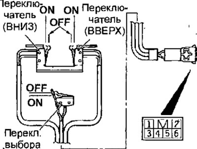
Fig. 13.38. Location of the contacts of the blocking switch
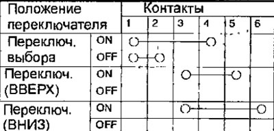
- If the conductivity between the connector contacts does not meet the required level, replace the switch.
Installation
- Installation is carried out in the reverse order of removal, taking into account the following.
Installing the selector lever lock cable (selector lever side)
- Temporarily set the selector lever button, move the selector lever to position P and turn the key in the ignition switch to the LOCK (OFF) position.
- Tighten the lock nut until the end of the selector lever lock cable protrudes above the red mark on the cam (fig. 13.34).
Tightening torque; 12 Nm
- Check the operation of the selector lever.
Installing the ignition switch lock cable (selector lever side)
- Install the ignition switch lock cable onto the lock mechanism cam.
- Install the ignition switch lock cable spring and washer.
- Lightly press the connection point of the cable to the locking mechanism cam in the direction of the arrow shown in figure 13.33, until the cable stops and tighten the lock nut.
Tightening torque: 12 Nm
- Check the operation of the selector lever.
Installing the gearbox control cable (gearbox side)
- Move the selector lever to position N.
- Make sure the ignition switch lock switch is in the N position.
- Pull the transmission control cable slightly in the direction of the arrow shown in figure 13.35, and tighten the nut.
Tightening torque: 12 Nm
- Make sure that the automatic transmission shifts into the mode corresponding to the selector lever position and operates correctly in that mode.
The original was published on the website (mitsubishiman.ru)
Checking the full throttle switch
- Disconnect the connector from the full throttle switch.
- Use an ohmmeter to check the conductivity between the contacts of the full throttle valve opening switch connector (Fig. 13.39). Make sure that there is conductivity between the contacts when the switch button is released, and there is no conductivity when pressed.
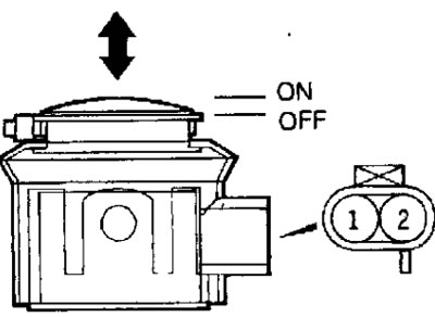
Fig. 13.39. Location of contacts of the connector of the full opening of the throttle valve switch