
Warning. To prevent damage to the gearbox mounting supports, connections in places cut off «*» in figures 13.41 and 13.43 should be pre-tightened, and the final tightening should be done after the engine is lowered onto the supports.
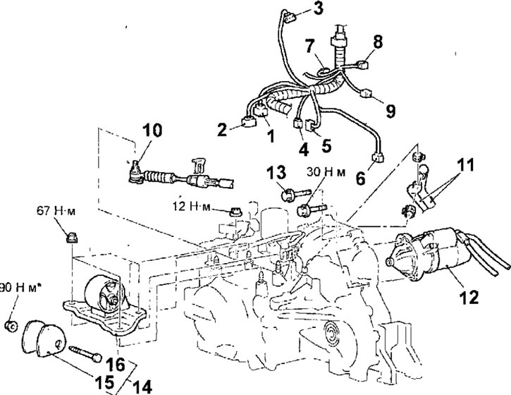
Pic. 13.41. Gearbox mounting elements: 1 - connector for ignition blocking switch: 2 - connector for automatic transmission control solenoid valves; 3- connector for air flow meter; 4 - input shaft speed sensor connector; 5 - output shaft speed sensor connector; 6 - vehicle speed sensor connector; 7 — a socket of the gauge of temperature of a cooling liquid; 8 - connector for the sensor of the coolant temperature indicator; 9 - knock sensor connector; 10 - tip of the gearbox control cable; 11 - transmission fluid heat exchanger hoses; 12 - starter; 13 - the upper bolts of the gearbox to the cylinder block, 48 Nm; 14 - gearbox support; 15 - gearbox support stopper; 16 - gearbox support bracket
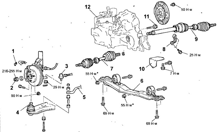
Pic. 13.43. Gearbox mounting elements: 1 - brake hose retainer; 2-nut for fastening the drive shaft; 3 - ball joint of the tie rod end; 4 - ball joint of the lower arm; 5-roll bar; 6 - central beam assembly; 7 - left drive shaft; 8 - bearing bracket; 9 - right drive shaft; 10 - cover; 11 - lower gearbox mounting bolts; 12 - gearbox
Removing
- Remove the bottom protective cover.
- Drain the coolant from the engine cooling system.
- Drain the transmission fluid from the transmission.
- Turn out bolts and remove a casing of the engine.
- Remove the air filter assembly.
- Remove the battery and its support.
- Turn away nuts and disconnect a reception exhaust pipe of an exhaust manifold.
- Disconnect the connectors from the ignition lock switch, automatic transmission control solenoid valves, air mass meter, input speed sensor, output speed sensor, vehicle speed sensor, coolant temperature sensor, coolant temperature gauge sensor, and knock sensor (pic. 13.41).
- Remove the cotter pin and disconnect the end of the transmission control cable from the selector lever.
- Disconnect the transmission fluid heat exchanger hoses.
- Unscrew the bolts and remove the starter and, without disconnecting the wires from it, fix it in a place where it will not interfere with the removal of the gearbox.
- Turn out the top bolts of fastening of a transmission to the block of cylinders.
- Carefully lift the transmission with a hydraulic jack, then remove the nut, remove the bolt and remove the transmission support.
- To support the engine, install a special tool on the car (motor hoist with manual hoist and traverse) pic. 13.42.
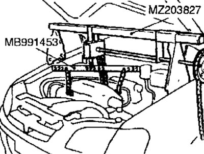
Pic. 13.42. Using a traverse to lift the engine from the engine compartment
- Remove the engine mount.
- Raise the car on a lift.
- Remove the retainer securing the brake hose to the front suspension strut (pic. 13.43).
- Loosen the nut securing the drive shaft to the front wheel hub.
- Remove the cotter pin and loosen the nut securing the ball joint pin of the tie rod end to the steering knuckle.
Warnings
- Do not loosen the nut securing the ball joint pin of the tie rod end to the steering knuckle. To prevent damage to the threads on the ball joint pin, use the special tool MB991113 or MB990635.
- To prevent the special tool MB991113 or MB990635 from falling off the cords, fix it on the front suspension strut.
- Install the special tool MB991113 or MB990635 as shown in Figure 13.44, making sure that the jaws of the tool are parallel. Turn the special tool bolt to push the ball joint pin out of the steering knuckle, then loosen the nut and remove the ball joint pin from the steering knuckle.
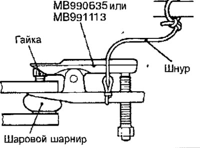
Pic. 13.44. Using a special tool to extrude the ball joint trunnion from the steering knuckle
- Loosen the nut, remove the bolt and lower arm ball joint pin from the steering knuckle.
- Turn away nuts and get bolts of fastening of the stabilizer of cross-section stability to the bottom levers. Turn out bolts and remove clips of fastening of the stabilizer bar, then remove the stabilizer from the car.
- Turn away nuts, get bolts and remove the central beam in gathering.
- Insert a pry bar between the left drive shaft inner CV joint and the gearbox and lightly tap the pry bar to remove the drive shaft from the gearbox.
Warnings
- Use the pry bar very carefully so as not to damage the hinge and the gearbox housing.
- Do not insert the mount very deeply. not to damage the differential seal.
- Do not pull on the drive shaft as this will damage the constant velocity joints.
- Turn out bolts and remove an arm of the bearing of the right power shaft.
- Remove the right drive shaft from the gearbox.
- Together with the hubs and steering knuckles, take the drive shafts away from the gearbox.
Warning. Do not disconnect the drive shafts from the steering knuckles and hubs.
- Using soft wire, secure the removed drive shafts inside the wheel arches so as to prevent the CV joints from being strongly bent.
- Install special plugs instead of drive shafts so that dirt does not get into the gearbox.
Warning. Replace the differential seal each time the drive shaft is removed.
- Turn out bolts and remove a cover.
- Turning the crankshaft of the engine, unscrew the bolts securing the torque converter drive plate.
- Press the torque converter towards the gearbox so that it does not remain on the engine.
- Remove the lower gearbox mounting bolts and lower the gearbox to the floor.
Installation
- Installation is carried out in the reverse order of removal, taking into account the following.
- Install the anti-roll bar and tighten the self-locking nut so that the stabilizer mounting bolt protrudes above the nut as shown in Figure 13.45.
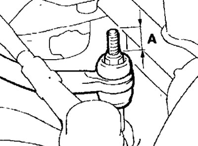
Pic. 13.45. Distance (A) bolt protrusion stabilizer mount: A = 22 mm
- Install the gearbox stopper so that the arrow on the flange points in the direction shown in Figure 13.46.
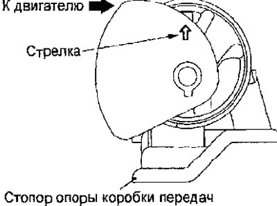
Pic. 13.46. Installing the gearbox retaining flange
- Connect the transmission control cable to the transmission and secure it with a cotter pin.
- Connect the exhaust pipe to the exhaust manifold.
- Install the battery and its support.
- Install the air filter assembly.
- Install the engine cover.
- Pour transmission fluid into the gearbox.
- Pour coolant into the engine cooling system.
- Install the lower protective cover.
- Check and, if necessary, adjust the wheel alignment.