



Contents: Removal ⤓ Installation ⤓
Warning: To prevent damage to the gearbox mounting supports, the connections at the locations marked with "*" in Figures 12.26 and 12.27 should be pre-tightened and final tightening should be performed after the engine has been lowered onto the supports.
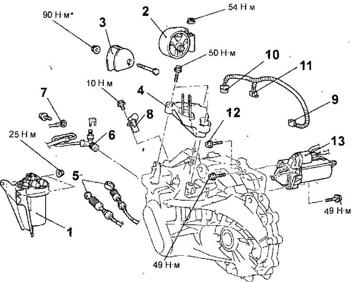
Fig. 12.26. Fastening elements of the F5MV1 and F5M42 gearboxes produced since 2000: 1 - fuel filter; 2 - gearbox support bracket; 3 - gearbox support stopper; 4 - lower gearbox support bracket; 5 - gearbox control cables; 6 - clutch slave cylinder; 7 - ground connection wire; 8 - crankshaft position sensor; 9 - vehicle speed sensor connector; 10 - Reverse light switch connector; 11 - harness connector control wire and auxiliary wiring; 12 - upper gearbox to cylinder block mounting bolts, 50 Nm; 13 - starter
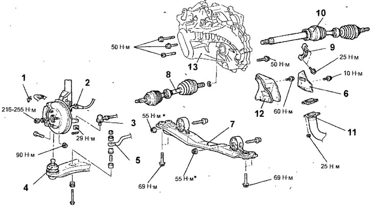
Fig. 12.27. Fastening elements of the F5MV1 and F5M42 gearboxes produced since 2000: 1 - brake hose fastening clamp; 2 - Wheel speed sensor connector (cars with ABS); 3 - ball joint of the steering rod end; 4 - lower arm ball joint; 5 - anti-roll bar; 6 - heat-protective casing; 7 - central beam assembly; 8 - left drive shaft; 9 - bearing bracket; 10 - right drive shaft; 11 - exhaust inlet pipe; 12 - rear support of the power unit; 13 - gearbox
Removal
- Disconnect the cable from the negative battery terminal.
- Drink transmission fluid from the gearbox.
- Remove the lower protective cover.
- Remove the air filter assembly.
- Remove the battery and its support.
- Remove the intercooler hose.
- Remove the fuel filter (Fig. 12.26).
- To support the engine, install a special tool on the vehicle (engine lift with a hand hoist and a crossbar) (see fig. 12.17).
- Unscrew the nut, remove the bolt and remove the gearbox support bracket.
- Using a hydraulic jack, carefully lift the gearbox, then remove the bolts and remove the lower gearbox support bracket.
- Remove the cotter pins and disconnect the gear selection and shift cables from the gearbox.
- Remove the clutch hydraulic drive slave cylinder and, without disconnecting the hose from it, secure it in a place where it will not interfere with the removal of the gearbox.
- Remove the bolt and disconnect the ground wire from the gearbox.
- Disconnect the connectors from the crankshaft position sensor, reverse light switch and vehicle speed sensor, as well as the harness connector control wire and auxiliary wiring.
- Remove the upper bolts securing the gearbox to the cylinder block.
- Unscrew the bolts and remove the starter and, without disconnecting the wires from it, secure it in a place where it will not interfere with the removal of the gearbox.
- Raise the car on a lift.
- Remove the retainer securing the brake hose to the front suspension strut (Fig. 12.27).
- On a vehicle with ABS, disconnect the connector from the wheel speed sensor.
- Remove the cotter pin and loosen the nut securing the ball joint pin of the tie rod end to the steering knuckle.
Warnings!
- Do not unscrew the nut securing the ball joint pin of the tie rod end to the steering knuckle. To avoid damaging the threads on the ball joint pin, use the special tool MB991113 or MB990635.
- To prevent the special tool MB991113 or MB990635 from falling, secure it to the front suspension strut with a cord.
- Install the special tool MB991113 or MB990635 as shown in figure 12.19, making sure that the jaws of the tool are parallel. Rotate the bolt of the special tool to push the ball joint pin out of the steering knuckle, then unscrew the nut and remove the ball joint pin from the steering knuckle.
- Loosen the nut, remove the bolt and the lower arm ball joint pin from the steering knuckle.
- Remove the nuts and bolts securing the stabilizer bar to the lower control arms. Remove the bolts and clamps securing the stabilizer bar, then remove the stabilizer bar from the vehicle.
- Remove the bolts and heat shield.
- Loosen the nuts, remove the bolts and remove the center beam assembly.
- Loosen the nuts and disconnect the exhaust pipe from the exhaust manifold.
- Insert a pry bar between the inner CV joint of the left drive shaft and the gearbox and lightly tap the pry bar to remove the drive shaft from the gearbox (see fig. 12.24).
Warnings
- Use the pry bar very carefully to avoid damaging the joint and gearbox housing.
- Do not insert the pry bar too deeply to avoid damaging the differential seal.
- Do not pull on the drive shaft as this will damage the constant velocity joints.
(The article is reprinted from a web resource: www.mitsubishiman.ru)
- Remove the bolts and the right drive shaft bearing bracket.
- Remove the right drive shaft from the gearbox.
- Remove the drive shafts from the transmission together with the hubs and steering knuckles. Do not disconnect the drive shafts from the steering knuckles and hubs.
- Use soft wire to secure the removed drive shafts inside the wheel arches so as to prevent the CV joints from being severely bent.
- Install special plugs instead of drive shafts to prevent dirt from getting into the gearbox.
Warning: Replace the differential seal whenever the drive shaft is removed.
- Remove the bolts and the rear powertrain support.
- Remove the lower bolts securing the gearbox to the cylinder block.
- Pull the transmission away from the engine and remove it from the vehicle. When separating the transmission from the engine, be careful not to damage the transmission input shaft, the clutch release bearing guide sleeve, and the clutch driven disc.
Installation
- Installation is carried out in the reverse order of removal, taking into account the following.
- Install the stabilizer bar and tighten the self-locking nut so that the stabilizer bar mounting bolt protrudes above the nut as shown in figure 12.21.
- Install the gearbox stop so that the arrow on the flange points in the direction shown in Figure 12.28.
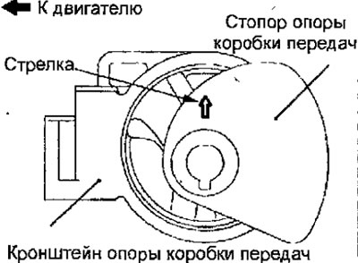
Fig. 12.28 Installing the gearbox locking flange
- Connect the gear selector and shift cables to the gearbox and secure them with cotter pins.
- Install the nozzle of the inflated air intercooler.
- Install the battery.
- Install the air filter assembly.
- Install the lower engine compartment cover.
- Fill the gearbox with transmission oil.
- Check that the gear shift lever moves smoothly and correctly through all positions.
- Check the operation of the speedometer.