



Contents: Purge control valve ⤓ Thermovalve ⤓ Overflow limiter (two-way valve) ⤓ Gravity valve ⤓ Carbon filter ⤓
Purge control valve
Check the condition of all hoses and connections. Many problems often arise due to unreliable connections in the system or limited hose capacity.
Check the valve (1) by removing the valve from the vehicle and connecting a hand vacuum pump to the vacuum port of the valve. The valve should maintain a vacuum.
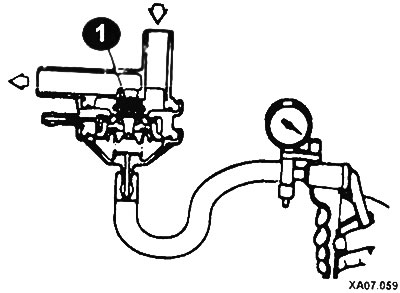
Reduce the vacuum and apply a low pressure air flow into the hose connection located on the side surface of the filter.
If there is no vacuum, air should not pass through the valve. Reduce the vacuum to 150 mm Hg. Re-supply air to the pipe. Air should pass through the valve.
The carbon filter is controlled by a purge control solenoid valve. With the engine off, disconnect the two vacuum hoses leading to the valve.
Disconnect the electrical supply wire from the valve. Connect a hand vacuum pump to the nozzle to which the hose was connected. Create some vacuum using the pump; it must be preserved.
Connect the battery to the solenoid valve terminals.
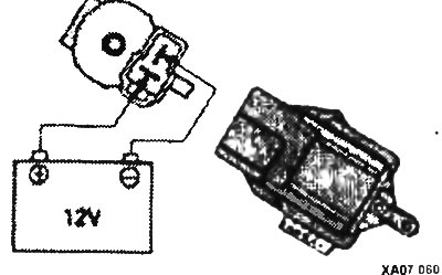
The polarity must be observed absolutely precisely. Connect the positive terminal to the terminal that forms the "top" of the "T". After applying voltage to the solenoid valve, the vacuum should decrease as the hand pump operates.
Disconnect the battery and check the resistance at the terminals of the solenoid valve. The resistance value should be 36-44 Ohms at a temperature of 20°.
CAUTION: Remember that the resistance value changes depending on temperature.
Thermovalve
Thermal valves are mounted on the intake manifold or cylinder head so that their bottom is immersed in the coolant (On later engine models, the purge system is controlled by the fuel injection computer). The thermal valve ensures that the vacuum to the purge control valve is delayed or passed, depending on the coolant temperature. Check on a cold engine.
Disconnect the two vacuum hoses at the thermostat valve. With the engine off, connect a hand vacuum pump to the upper port on dual port valves or to the single port.
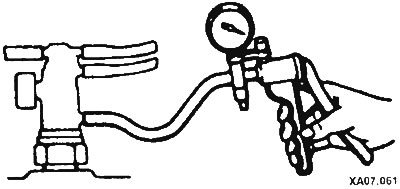
Apply vacuum and verify that the valve is leaking or does not retain vacuum.
Start and warm up the engine. After the coolant has warmed up to operating temperature, disconnect the corresponding hose and repeat the check. The valve should maintain a vacuum.
Replace the thermal valve only on a cold engine.
Overflow limiter (two-way valve)
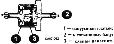
Elements of a two-way valve
This device, sometimes mistaken for a fuel filter, is installed on the steam line leading from the tank to the carbon filter. Located on or near the tank, this valve is sensitive to both compression and vacuum. It is designed to compensate for pressure differences that occur in the tank.
When excess pressure is created in the tank, for example, at high air temperatures or after driving a significant distance, the valve releases pressure and vapors into the carbon filter, thereby ventilating the tank and preventing an increase in the level of vapors. Conversely, when a vacuum is created in the tank, the valve will release some air from the filter into the tank.
NOTE: If you hear a noise coming from the rear of your vehicle (even with the engine off), this is the sound of this valve releasing pressure. To eliminate this noise, unscrew the fuel filler cap and screw it back on.
Replacing the valve can only change the tone of the sound, but the sound itself is preserved in most cases.
To check, do the following:
- Remove the valve from the steam line.
- Lightly blow through the valve on each side. If air passes through with some resistance, the valve is functional.
- Connect the valve to the main line in the appropriate direction and secure the clamps. Before installing the clamps, make sure that the main lines are securely installed on the nozzles.
Gravity valve
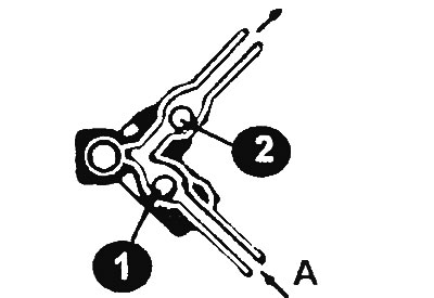
This valve is located in the steam line leading from the tank to the carbon filter. The valve prevents gasoline from leaking from the fuel tank into the system if the vehicle rolls over in a traffic accident. Under normal conditions, this line supplies vapors that are easily absorbed and retained by the carbon mass of the filter.
When the car turns over, the line fills with liquid gasoline. Therefore, the gravity valve closes the fuel line and keeps the fuel in the tank.
To check, remove the valve and disconnect the hoses from it. If you hear clicks when shaking it, it is working properly.
Carbon filter
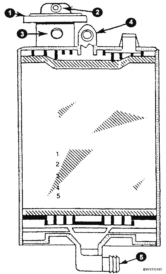
Typical elements of a carbon filter (fuel vapor collection tank)
1 - tank purge valve; 2 - branch pipe of the valve control cavity for connecting the vacuum hose; 3 - purge line branch pipe; 4 - branch pipe for connecting the hose for removing gasoline vapors from the tank; 5 - air inlet pipe.
The carbon filter should be checked periodically for cracks, blockages and hose connections. On many models, the carbon filter is replaced after a certain period of time or a certain number of kilometers.