



Contents: Removal ⤓ Installation ⤓
Removal
1. Drain the fluid from the power steering hydraulic drive.
2. Disconnect the cable from the negative terminal of the battery.
3. Remove the cross beam.
4 Remove the intake pipe of the exhaust system.
5. Remove the bolt connecting the steering shaft and the steering gear pinion shaft (Fig. 16.17).
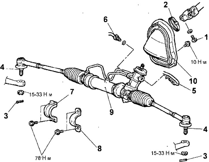
Fig. 16.17. Steering gear: 1 - connecting bolt of steering shaft and steering gear, 17 Nm; 2 - clamp; 3 - cotter pin; 4 - steering rod ends; 5 - return hose, 12-14 Nm; 6-pressure hose, 12-14 Nm; 7-steering gear mounting bracket; 8 - Steering gear housing mounting bracket; 9 - steering gear assembly; 10 - protective cover assembly
6. Loosen and remove the clamp.
7. Remove the cotter pins and unscrew the nuts securing the ball joint pins of the steering rod ends to the steering knuckles. Using a special tool, disconnect the steering rod end from the steering knuckle (Fig. 16.3).
Warning. Do not completely loosen the nut securing the ball joint pin of the tie rod end to the steering knuckle. Use a special tool to prevent damage to the threads on the ball joint pin. To prevent the special tool MB991113 or MB990635 from falling, secure it to the front suspension strut with a cord.
8. Loosen the clamp and disconnect the return hose.
9. Loosen the clamp and disconnect the pressure hose.
10. Unscrew the two bolts and remove the steering gear mounting bracket.
11. Unscrew the two bolts and remove the steering gear housing mounting bracket.
12. Remove the steering gear assembly. When removing the steering gear assembly, be careful not to damage the protective boots on the steering gear and tie rod ends.
13. Remove the protective cover assembly. Make sure there are no cracks or damage to the rubber parts.
Checking the total torque of the steering gear pinion
1. Secure the steering gear in a vice with jaws covered with soft material.
2. Measure the total torque of the steering gear pinion by turning the pinion with a special tool (09565-11100) one revolution every 4-6 seconds (Fig. 16.18).
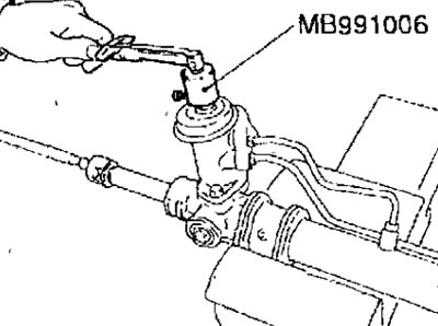
Fig. 16.18. Checking the total torque of the steering gear pinion
Total torque of the steering gear pinion:
- cars with petrol engines: 0.6-1.3 Nm (deviation: 0.4 Nm)
- diesel engine car: 0.5-1.2 Nm (deviation: 0.4 Nm)
Warning: When clamping the steering gear in a vice, clamp it only at the mounting points. If the steering gear is clamped at other points, the steering gear housing may be deformed or damaged.
Note: Measure the preload at full rack travel.
3. If the total torque of the steering pinion does not meet the required values, first adjust the tightening torque of the plug and recheck.
4. If adjusting the plug tightening torque does not produce positive results, check or replace the rack stop elements.
Checking the resistance to steering rod deflection
1. Perform 10 steering rod deflections.
2. Use a dynamometer to measure the force required to deflect the steering rod (Fig. 16.19).
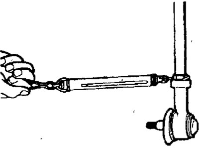
Fig. 16.19. Checking the resistance to steering rod deflection
Steering rod deflection force: 6-20 N
3. If the measured value exceeds the standard value, replace the steering tie rod assembly.
4. If the measured value is below the nominal value and the steering rod turns smoothly and without play, it can be installed on the vehicle.
Checking the dust cover of the ball joint of the steering rod end
1. Use your fingers to squeeze the dust cover and check for cracks or damage.
2. If the dust boot is cracked or damaged, replace the tie rod end. If the dust boot is cracked or damaged, the ball joint may also be damaged.
Adjusting the overall torque of the steering gear pinion
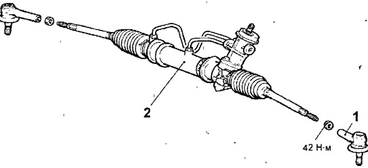
Fig. 16.20. Steering gear: 1 - steering rod end; 2 - steering gear
1. Set the rack to the central position. Tighten the rack stop cover to a torque of 15 N·m.
2. In the neutral position, use a special key to turn the pinion shaft clockwise one revolution in 4-6 seconds (see Fig. 16.18). Unscrew the rack stop cover by 30-60° and adjust the rotation torque of the steering gear pinion to the nominal value.
3. Measure the total torque of the steering gear pinion by turning the pinion with a special tool (09565—11100) one revolution every 4-6 seconds (Fig. 16.21).
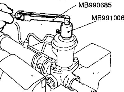
Fig. 16.21. Adjusting the total torque of the steering gear pinion
Total torque of the steering gear pinion:
- cars with petrol engines: 0.6-1.3 Nm (deviation: 0.4 Nm)
- diesel engine car; 0.5-1.2 Nm (deviation: 0.4 Nm)
If adjustment is not possible within the specified pinion shaft rotation angle, check or replace the rack stop parts and rack stop covers.
4. After completing the adjustment, tighten the rack stop cover lock nut.
Installing the tie rod end
1. Tighten the left and right tie rod ends to the size shown in Figure 16.22 and tighten the lock nuts.
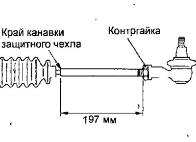
Fig. 16.22. Control dimension for installation of left and right steering rod ends
Replacing the ball joint dust cover of the steering rod end
Only if the dust cover is damaged accidentally during vehicle maintenance, replace it as follows.
1. Using a screwdriver blade, remove the snap ring and dust cover from the steering tie rod ball joint.
2. Apply universal grease 3M ATD No.8661 to the inner surfaces of the new dust cover.
3. Using a special tool, install the protective cover on the ball joint pin of the steering rod end (Fig. 16.23).
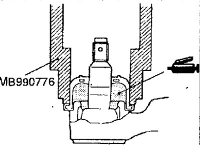
Fig. 16.23. Using a special tool to install a protective boot on the ball joint pin of the tie rod end
4. Use your fingers to squeeze the dust cover and check for cracks or damage.
Installation
1. Installation is carried out in the reverse order of removal, taking into account the following.
2. Pour the liquid into the tank up to the base of the oil filter.
3. Bleed the power steering hydraulic drive.
4. After setting the wheels to the straight-ahead position, check the position of the steering wheel.