



Clean the backs of the new main bearing inserts and place the halves with the oil hole on the main bearing seats in the cylinder block.
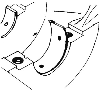
Install the other halves of each set into their respective bearing caps, making sure that the key of each bearing fits into the cutout in the cylinder block or cap.
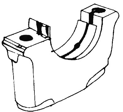
CAUTION: Do not hammer or scratch the bearing faces. No lubrication is required at this time.
Wipe the bearing seating surfaces in the block and the crankshaft journals with a clean cloth. Check or clean the oil holes in the crankshaft.
Carefully place the crankshaft on the main bearings. Before finally installing the crankshaft, it is necessary to check the oil clearance of the main bearings, which is determined by simply measuring the seat diameters or using a special measuring plastic.
Cut off several pieces of plastic of a suitable size to measure the clearance (they should be slightly shorter than the width of the main bearings) and place one piece on each main journal of the shaft parallel to its axis.
Clean the bearing surfaces in the caps and install the caps in their places. Do not move the plastic. Apply a little oil to the bolt threads.
Tighten the main bearing cap bolts in three stages to the specified torque. Do not turn the crankshaft during this operation.
Loosen the bolts and carefully remove the bearing caps.
Compare the width of the crushed plastic on each neck with the scale printed on the bag of plastic and determine the gap. Compare the results with the technical data.
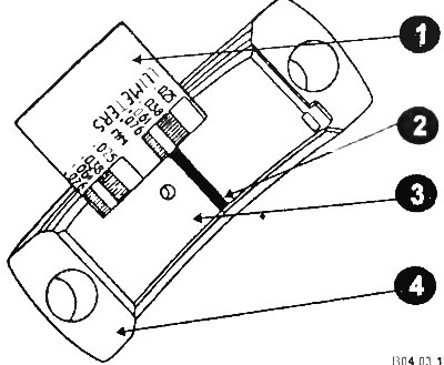
1 - scale; 2 - plastic wire; 3 - insert; 4 - contact surface of the cover.
ATTENTION: The plastic bag has scales in mm and inches, do not mix them up.
If the gap is not normal, the bearings may not be the right size. Before deciding whether to replace the bearings, check to see if dirt or oil has gotten between the bearing and the cover. If one end of the plastic for measuring the gap is significantly wider than the other, the neck may be tapered.
Carefully clean all traces of clearance plastic from journals and bearings. Be careful not to scratch bearing surfaces.
The liners are selected according to the marks and color coding applied to the crankshaft and lower connecting rod head.
4-cylinder engine marks
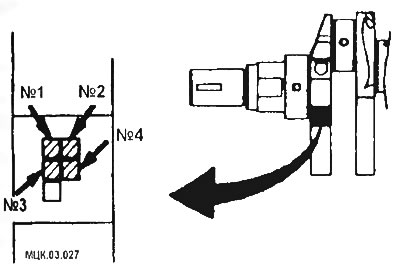
Crankshaft marks
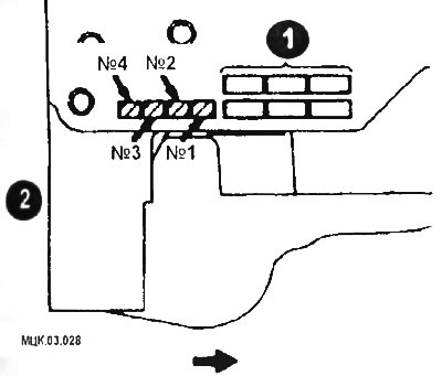
Cylinder Block Marks
6-cylinder engine marks
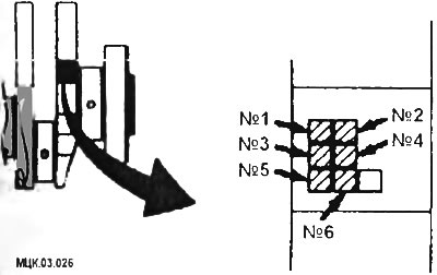
Identification marks of connecting rod bearings (engine 6A12)
Final installation of the crankshaft
Carefully remove the crankshaft from the engine. Clean the bearing surfaces in the block, then apply a uniform layer of engine oil to them.
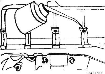
Lubricate the crankshaft surfaces in contact with the seals with clean engine oil.
Make sure the crankshaft journals are clean, then place the shaft back in the cylinder block.
Clean the bearing surfaces in the caps and apply grease to them.
Install the covers in their places so that the marks on the covers are on the generator side.
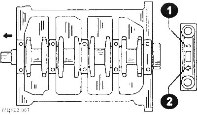
Crankshaft main bearing cap marks
1 - cover number; 2 - arrow pointing to the front of the engine.
(The original article is on: «MITSUBISHIMAN.ru»)
CAUTION: Before installing the caps, check the liners in the cap beds again. The 3rd bearing should have no oil groove, while the others should have one.
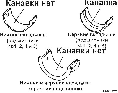
4-cylinder engine liners
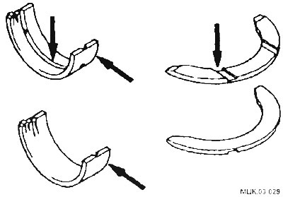
6-cylinder engine liners
Apply a thin coat of oil to the threads and underside of the bolt heads, then install them.
Tighten all main bearing cap nuts except thrust bearing cap number 3 to the specified torque value. Move the shaft back and forth to seat the thrust bearing shells, and then tighten the number 3 cap nuts to the specified torque value.
Measure the shaft play using feeler gauges or an indicator (see above).
Turn the crankshaft by hand several times and check if it is seizing.
Using a mandrel, press the oil seal into the rear cylinder block cover.
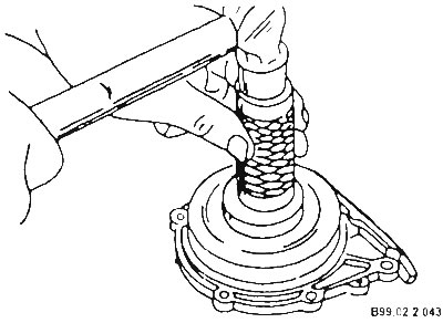
Using a drift, place the rear cylinder block cover (oil seal) onto the crankshaft journal and secure the cover to the block.