



Remember that the mark (arrow) on the piston head must face the front of the engine (camshaft drive).
Wipe the cylinders with a clean, lint-free cloth.
Apply lubricant to the piston rings and then install the ring compressor onto the first piston to be installed.
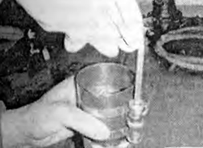
If you don't have a squeezer, you can use a hose clamp of a suitable size.
Devices used to install piston assemblies with rings into engine cylinders
(The original material is here MitsubishiMan)
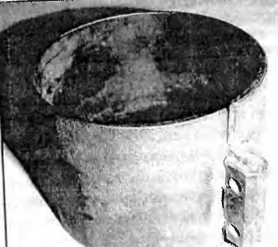
Universal (adjustable) bushing - general view
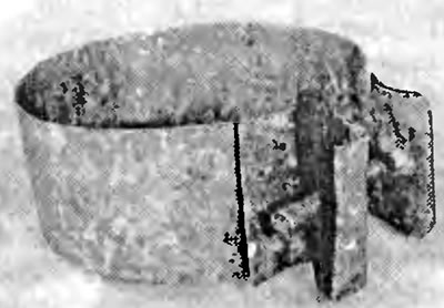
The simplest device made from a metal strip (like a clamp)
Connecting rod bearings - installation on the crankshaft
Before installing the pistons with connecting rods, the walls of the block grooves must be thoroughly cleaned and the crankshaft installed in place.
Remove the cap from connecting rod number 1 (the caps should have marks made during removal).
Clean the back of the new upper bearing shell, then slide it into place in the connecting rod. Make sure the key on the shell fits into the recess in the connecting rod. Do not hammer the shell or scratch the bearing surface. Do not lubricate the bearing yet.
Clean the back of the second bearing and install it into the cap. Make sure the bearing key fits into the cap recess, but do not apply grease yet.
Place a piece of plastic or rubber tubing over each connecting rod cap bolt.
With the piston oriented so that the arrow on its top points forward (camshaft drive), carefully insert the piston with the connecting rod into the first cylinder.
Gently press the top of the piston with a wooden block, while simultaneously guiding the end of the connecting rod into its place on the crankshaft journal. Work slowly, and if you feel resistance, stop immediately. Find out the cause and eliminate it. Do not press hard on the piston under any circumstances - you can damage the seats.
After the piston and connecting rod are installed, it is necessary to check the size of the connecting rod bearing oil clearance before the connecting rod is finally screwed into place.
Cut a piece of appropriately sized plastic clearance gauge slightly shorter than the width of the connecting rod bearing and place it on the number 1 crankpin, parallel to its axis.
Clean the surface of the connecting rod bearing cap, remove the protective tubes from the connecting rod bolts and install the connecting rod cap.
Install the nuts and tighten them to the specified torque value in three stages. Do not rotate the crankshaft while doing this.
Unscrew the nuts and remove the connecting rod cover, being careful not to damage the plastic.
Compare the width of the crushed plastic to measure the gap with the scale on its package to determine the gap. Compare the obtained value with the technical data.
If the clearance is not within specification, the bearing shells may be the wrong size. But before you decide to replace the shells, check to see if any dirt or oil has gotten between the shells and the connecting rod or cap. Also, check the journal diameter. If the width of the plastic for measuring the clearances is different at each end of the strip, the journal may be tapered and need to be reground.
Final installation of the connecting rod
Carefully clean all traces of clearance measuring plastic from the journal and bearing surface, being careful not to scratch the bearing.
Make sure the bearing surfaces are completely clean and apply a uniform coat of grease to both bearings. You will have to push the piston into the bore to gain access to the connecting rod bearing - remember to pull the protective tubes onto the connecting rod bolts first.
Place the connecting rod on the shaft journal, remove the protective tubes from the connecting rod cap bolts, install the cap and tighten the nuts in three steps to the required tightening torque.
Repeat the above procedure for the remaining pistons and connecting rods.
Check the piston assembly.
Once all pistons and connecting rods are installed, turn the crankshaft by hand several times and check for binding.
Check the play of the connecting rods.
Compare the measured clearance with the technical data. If the clearance was within the norm before disassembly, and the old connecting rods and crankshaft were used, it should remain within the norm. If new connecting rods or a new crankshaft were installed, the clearance may not correspond to the norm. In this case, it is necessary to remove the connecting rods and send them to a workshop for mechanical processing.