
2. Insert a paper clip from the side of the wires into the 1st pin of the tachometer connector (pic. 3.9).
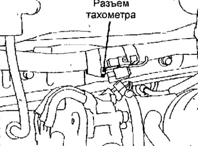
Fig.3.9. Tachometer connector location
3. Connect the tachometer wire to the paper clip installed in the connector.
Attention. Do not use the MUT-II. If the MUT-II device is connected to the diagnostic connector, it will show the current ignition timing, and not the main one.
4. Connect the stroboscope in accordance with its instruction manual.
5. Start the engine and let it idle.
6. Check idle speed
Engine idle speed: 750±100 min-1
7. Turn off the ignition.
8. Remove the waterproof plug from the brown main ignition timing socket.
9. Connect the jumper with a clip to the contact for adjusting the main ignition timing of the connector and connect the jumper with a clip «weight» (pic. 3.10).
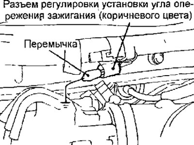
Pic. 3.10. Installing a jumper to check the main ignition timing
Note. Connecting this connector pin to «weight» puts the engine into operation at the main ignition timing.
10. Start the engine and leave it to idle.
11. Check the main ignition timing.
Basic ignition timing: 5±2°to TDC
12. If the main ignition timing does not match the required one, loosen the ignition distributor mounting bolt and, by rotating the ignition distributor, set the required main ignition timing.
13. After adjusting the main ignition timing, tighten the ignition distributor mounting bolt.
Tightening torque: 12 Nm
14. Turn off the engine and remove the jumper from the connector for adjusting the main ignition timing (Brown) and replace the waterproof plug.
15. Start the engine and check the ignition timing.
Ignition timing: approx. 10°BTDC
Note
(1) The ignition timing setting varies within±7°even during normal engine operation.
(2) The ignition advance automatically increases from approximately 5°to 10°as altitude increases.