
Removing
- Disconnect the wire from the negative battery terminal.
- Remove the air filter.
- Remove ignition coils.
- Disconnect the quarry ventilation hose from the fitting on the cylinder head cover. (pic. 3.47).
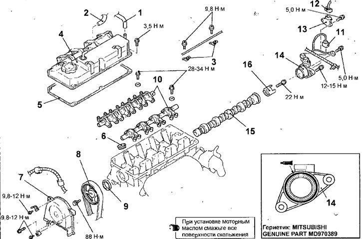
Pic. 3.47. Camshaft and camshaft oil seal of 4G13 engine:1 - crankcase ventilation hose; 2 - PCV hose; 3 - clamps for attaching the accelerator cable; 4 - cylinder head cover; 5 - cylinder head cover gasket; 6 - spark plug guide tube; 7 - front upper casing of the toothed belt; 8 - camshaft pulley; 9 - camshaft seal; 10 - axis of rocker arms assembled with rocker arms; 11 - camshaft position sensor connector; 12 - connector for the misfire detection sensor; 13 - misfire detection sensor; 14 - base of the camshaft position sensor; 15 - camshaft; 16 - camshaft position sensor rotor
- Disconnect the PCV hose from the fitting on the cylinder head cover.
- Turn out bolts and remove clips of fastening of a cable of an accelerator.
- Disconnect the connector from the camshaft position sensor and misfire detection sensor.
- Turn out bolts and remove a cover and a laying of a head of cylinders.
- Remove the fresh ignition guide tubes.
- Turn out bolts and remove a forward top casing of a gear belt.
- For the pulley mounting bolt, turn the crankshaft clockwise until the alignment mark on the camshaft pulley aligns with the corresponding mark, while the piston of the 1st cylinder will be set to TDC on the compression stroke (pic. 3.48).
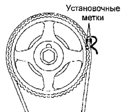
Fig.3.48. Combination of installation marks when installing the piston of the 1st cylinder at TDC in the compression stroke
- Fasten the toothed belt to the camshaft pulley with soft wire or band clamps, which will prevent the belt from moving relative to the camshaft pulley (pic. 3.49).
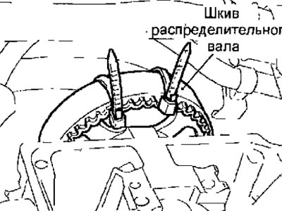
Pic. 3.49. Using two band clamps to secure the toothed belt to the camshaft pulley
- Using special tools MD998719 or MD998754 and MB990767, block the camshaft pulley from turning and remove the pulley mounting bolt (see fig. 3.20). Remove the pulley with the toothed belt attached to it from the camshaft.
Warning. Do not turn the crankshaft after removing the pulley from the camshaft.
- Punch a groove near the sealing lip with a knife or flathead screwdriver.
Warning. Be careful not to damage the camshaft and cylinder head.
- Insert a flat screwdriver blade wrapped in cloth into the punched groove, and, using a screwdriver as a lever, remove the oil seal.
- Loosen and then remove the rocker shaft mounting bolt, then remove the entire assembly with the bolt that should remain with the assembly.
Warning. Do not disassemble the rocker shaft assembly.
- Remove the bolts and remove the camshaft position sensor base.
- Remove the camshaft from the cylinder head.
- Remove the bolt and remove the camshaft position sensor rotor.
Installation
- Installation is carried out in the reverse order of removal, taking into account the following.
- Lubricate the camshaft journals and cams with engine oil.
- Install and bolt the camshaft position sensor rotor.
- Install the camshaft to the cylinder head.
- Install and bolt the camshaft position sensor base.
- Install and bolt the rocker axles.
- Lubricate the lip of the camshaft oil seal with engine oil.
- Using a special tool, press in the camshaft oil seal (see fig. 3.21).
- Install the camshaft pulley and secure with a bolt, tightening it to the required torque. Using special tools MD998719 or MD998754 and MB990767, block the camshaft pulley from turning and tighten the pulley mounting bolt to 88 Nm (see fig. 3.20).
- Install and bolt the front upper toothed belt guard.
- Install the spark plug guide tubes.
- Install and bolt the gasket and cylinder head cover.
- Connect the connectors to the camshaft position sensor and misfire detection sensor.
- Install and bolt the accelerator cable clamps.
- Connect the PCV hose to the fitting on the cylinder head cover.
- Connect the crankcase ventilation hose to the fitting on the cylinder head cover.
- Install the ignition coils.
- Install the air filter.
- Connect the wire to the negative battery terminal.