
Removing
- Disconnect the wires from the battery terminals.
- To remove the engine, perform the following steps in sequence.
- Relieve the fuel pressure in the fuel system. See chapter «Reducing the pressure in the fuel system», attached in the section «Multipoint fuel injection system (MPI)».
- Remove the hood.
- Remove the radiator.
- Remove the gearbox.
- Remove the lower engine mudguard.
- Remove the air filter.
- Remove the exhaust pipe.
- Turn out bolts and remove a clip of strengthening of a cable of an accelerator (pic. 3.44).
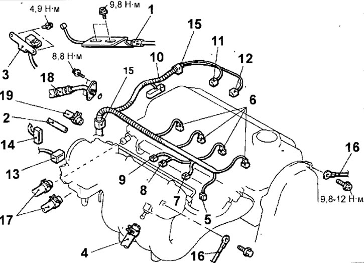
Pic. 3.44. Places for connecting connectors and hoses to the engine: 1 - clamp fastening the accelerator cable; 2 - vacuum hose; 3 - boost pressure sensor and bracket; 4 - vacuum hose of the vacuum brake booster; 5 - knock sensor connector; 6 - nozzle connector; 7 - connector for the temperature sensor of the air entering the engine; 8 - connector for the solenoid valve for cleaning the adsorber; 9 - connector for the exhaust gas recirculation solenoid valve; 10 - ignition distributor connector; 11 - coolant temperature sensor connector; 12 - connector for the sensor of the coolant temperature indicator; 13 - throttle position sensor connector; 14 - throttle control servo connector; 15-clamp for fastening the wiring harness; 16 - wire connecting the engine block with «weight»; 17 - heater hose; 18 - high pressure fuel hose; 19 - fuel return hose
- Disconnect the vacuum hose.
- Remove the bolts and remove the boost reduction sensor and bracket.
- Loosen the clamp and disconnect the brake booster vacuum hose.
- Disconnect the connectors from the knock sensor, injectors, engine air temperature sensor, canister purge solenoid valve, EGR solenoid valve, ignition distributor, throttle position sensor, throttle correction servo, coolant temperature sensor, and coolant temperature gauge sensor.
- Remove the clip and move the wiring harness away from the engine.
- Turn out bolts and disconnect wires of connection of the block of cylinders of the engine with «weight».
- Loosen the clamps and disconnect the engine and heater cooling system hoses.
- Turn out bolts, disconnect a fuel hose of a high pressure and remove an annular sealing lining.
- Loosen the clamp and disconnect the fuel return hose.
- Loosen and remove the power steering pump and A/C compressor drive belt (pic. 3.45).
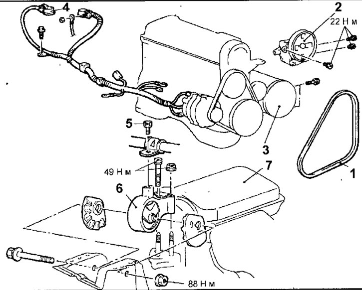
Pic. 3.45. Removable elements and engine mounting elements: 1 - drive belt for power steering pump and air conditioning compressor; 2 - power steering pump and bracket; 3 - air conditioner compressor; 4 - wires for connection to the battery terminals; 5 - bolt for fastening the hose of the hydraulic drive of the power steering pump, 12-14 N·m; 6 - engine bracket; 7 - engine
- Loosen the bolts and remove the power steering pump along with the attached hose and bracket.
Note. Use cord or soft wire to secure the removed power steering pump to the engine compartment so that it does not interfere with engine removal.
- Disconnect a socket, turn out bolts and remove the conditioner compressor from an arm together with the connected hoses.
Note. Secure the removed compressor in the engine compartment with a cord or soft wire so that it does not interfere with the removal of the engine.
- Turn out a bolt of fastening of a hose of a hydraulic drive of the pump of the amplifier of a steering.
- Place a hydraulic jack under the engine.
- Remove the special tool used to remove the transmission from the engine.
- Fasten the motor to the yoke and hang it from a hoist or similar device (pic. 3.46).
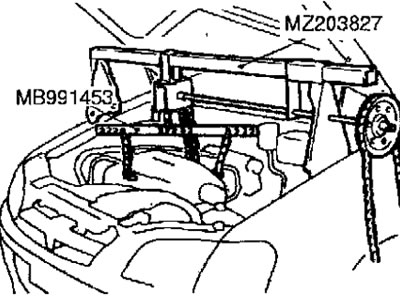
Pic. 3.46. Using a traverse to lift the engine from the engine compartment
- Insert a piece of wood between the jack foot and the engine oil pan and lift the engine slightly to relieve the weight of the engine support, then remove the engine support bracket.
- Check that all wires are disconnected from the engine (electrical connectors), hoses, etc., and then slowly lift the engine up from the engine compartment.
Installation.
- Installation is carried out in the reverse order of removal, taking into account the following.
- When installing the engine, make sure that the wires, hoses and wire connectors are not pinched.
- Substitute under the engine rolling; hydraulic jack (by inserting a block of wood between the jack foot and the engine oil pan) and install the engine support bracket while adjusting the engine position with a jack.
- While supporting the engine with a jack, disconnect the hoist.
- When installing the high pressure fuel hose, lubricate the O-ring with a small amount of clean engine oil (rice. 3.36). Do not allow oil to enter the fuel line.
- Slightly turning the fuel hose flange to the right or left, carefully insert it into the fuel line so as not to damage the O-ring. After installation, check that the hose turns smoothly in the fuel line.
- If the hose flange sticks when turning, the cause may be a damaged O-ring. Detach the flange (complete with hose) from the fuel line and check the gasket for damage, then reinsert it and check for smooth turning.
- Screw in the high pressure fuel hose mounting bolts and tighten them to 5 Nm.
- Connect and adjust the accelerator cable.