



If there are leaks in the intake manifold, the vacuum of air entering the engine is reduced, which leads to malfunction of one or more cylinders.
Removal
- Disconnect the cable from the negative battery terminal.
- Relieve the fuel pressure in the fuel system. See chapter "Reducing pressure in the fuel system", given in the section "Multi-Point Fuel Injection (MPI)".
- Drain the coolant from the engine cooling system.
- Remove the air filter.
- Remove the throttle assembly.
- Disconnect the PCV hose from the cylinder head cover pipe (Fig. 3.55).
- Disconnect the vacuum hose.
- Loosen the clamp and disconnect the brake booster vacuum hose.
- Disconnect the connectors from the knock sensor, injectors, engine air temperature sensor, purge solenoid valve and exhaust gas recirculation solenoid valve.
- Remove the control wiring harness from the engine.
- Remove the bolt and disconnect the wire connecting the cylinder head to the ground.
- Remove the bolts, disconnect the high pressure fuel hose and remove the O-ring seal (see fig. 3.36)
- Loosen the clamp and disconnect the fuel return hose.
- Unscrew the bolts and remove the fuel line, fuel return pipe, injectors and pressure regulator as an assembly (Fig. 3.56).
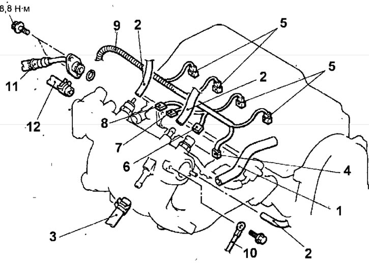
Fig. 3.55. Intake manifold of the 4G1-MPI engine: 1 - PCV crankcase ventilation hose; 2 - vacuum hose; 3 - brake booster vacuum hose; 4 - knock sensor connector; 5 - injector connectors; 6 - connector for the temperature sensor of the air entering the engine; 7 - connector of the electromagnetic valve for cleaning the adsorber; 8 - EGR solenoid valve connector; 9 - control wiring harness; 10 - wire connecting the engine cylinder block to the ground; 11 - High pressure fuel hose; 12 - fuel return hose
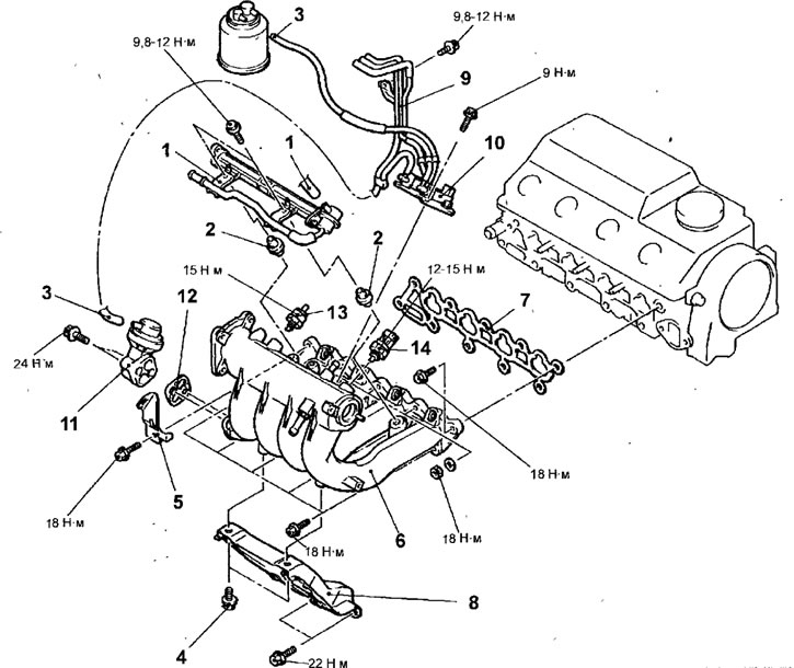
Fig. 3.56. Intake manifold of the 4G1-MP1 engine:1 - fuel line, fuel return pipe, injectors and pressure regulator; 2 - spacer sleeve; 3 - vacuum hose; 4 - upper intake manifold support mounting bolt, 18 Nm; 5 - bracket; 6 - intake manifold; 7 - intake manifold gasket; 8 - intake manifold support; 9 - vacuum hose and vacuum tube; 10 - electromagnetic valve unit; 11 - Exhaust gas recirculation (EGR) valve; 12 - gasket; 13 - filter, 13 Nm; 14 - engine air temperature sensor
Caution: When removing the fuel line, be careful not to let the fuel injectors fall out.
- Disconnect the vacuum hose from the exhaust gas recirculation (EGR) valve.
- Remove the upper intake manifold support mounting bolt.
- Remove the bolts and bracket.
- Remove the bolts and nuts and remove the intake manifold and intake manifold gasket.
- Remove the bolts and intake manifold support.
- Remove the vacuum hose and vacuum tube.
- Remove the bolts and solenoid valve assembly.
- Remove the bolts and EGR valve and gasket.
- Remove the filter and the temperature sensor of the air entering the engine.
Examination
- Check the intake manifold for cracks or other damage.
- Check the exhaust (vacuum) channel for blockages.
- Use a metal ruler and feeler gauges to measure the flatness of the intake manifold mating surface.
Deviation from flatness of the intake manifold mating surface:
- nominal: no more than 0.15 mm
- maximum permissible: 0.20 mm
(Original source of information mitsubishiman.ru)
Installation
- Installation is carried out in the reverse order of removal, taking into account the following.
- When installing the fuel hose (high pressure), lubricate the O-ring with a small amount of clean engine oil (Fig. 3.36).
Warning: Do not allow oil to enter the fuel line.
- While slightly turning the flange of the fuel hose to the right and left, carefully insert it into the fuel line so as not to damage the O-ring seal. After installation, check that the hose rotates smoothly in the fuel line.
- If the hose flange jams when turning, damage to the O-ring gasket may occur. Disconnect the flange (complete with hose) from the fuel line and check the gasket for any damage, then insert it back and check that it turns smoothly.
- Install the high pressure fuel hose mounting bolts and tighten them to the specified torque.
- Install the throttle assembly.
- Install the air filter.
- Fill the engine cooling system with coolant.
- Connect the cable to the negative terminal of the battery.