
Input shaft
1. Check the outer surface A of the input shaft at the place where the needle bearing is installed for damage, excessive wear, pitting (pic. 11.25).
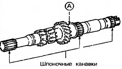
Pic. 11.25. Check input shaft outer surface A at needle bearing mounting location for damage, excessive wear, pitting
2. Check the keyways for damage and wear.
Needle bearing
3. Assemble the needle bearing together with the shaft or bearing shell and gear, and check that the needle bearing rotates without noise or wobble.
4. Check the needle bearing cage for deformation (pic. 11.26).
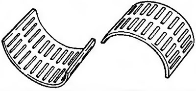
Pic. 11.26. Check the needle bearing cage for deformation
Synchronizer ring
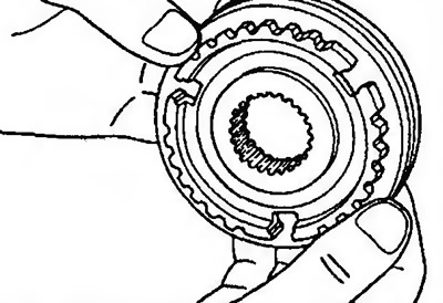
5. Check the coupling ring gear for damage and breaks. Check the inside surface for damage, wear and thread distortion (pic. 11.27).
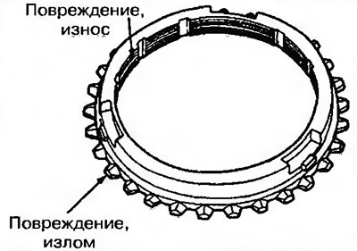
Pic. 11.27. Check the clutch ring gear for damage and breaks. Check the inside surface for damage, wear and thread distortion
6. Press the synchronizer ring against the ring gear of the drive gear and check clearance A (pic. 11.28). Nominal value: 0.5 mm.
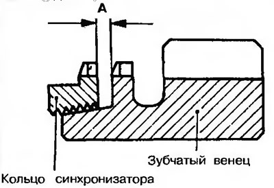
Pic. 11.28. Press the synchronizer ring against the ring gear of the drive gear and check clearance A
Gear Clutch and Synchronizer Hub
7. Assemble the clutch and synchronizer hub together and check that they slide smoothly into each other (pic. 11.29).
Pic. 11.29. Assemble the clutch and synchronizer hub together and check that they slide smoothly into each other
8. Check that the engagement clutch is not damaged on the inside front and rear.
9. Check the synchronizer hub on both sides for wear (contact surface with drive gears).
Attention! If the hub is replaced, it must be replaced complete with the gear engagement clutch.
Drive gears
10. Check the smoothness of the surface of the synchronizer cone, the absence of damage and wear (pic. 11.30).
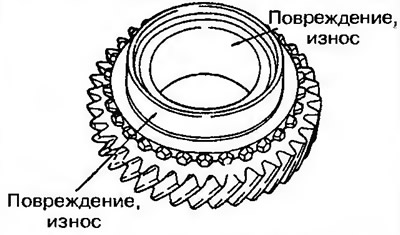
Pic. 11.30. Check the smoothness of the surface of the synchronizer cone, the absence of damage and wear