
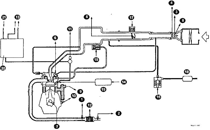
Schematic diagram of the fuel injection system (GDI)
1 - front oxygen sensor; 2 - rear oxygen sensor; 3 - air flow sensor; 4 - air temperature sensor but the intake manifold; 3 - to the throttle position sensor; 6 - camshaft position sensor; 7 - crankshaft position sensor: 8 - atmospheric air pressure sensor; 9 - coolant temperature sensor; 10 - knock sensor; 11 - fuel pressure sensor; 12 - throttle position sensor; 13 - into the fuel tank; 14 - injector control unit; 13 - exhaust gas recirculation valve; 16 - solenoid valve for adsorber purge; 17 - throttle servo; 18 - adsorber; 19 - nozzle; 20 - high pressure fuel pump (injection pump); 21 - from the low pressure fuel pump.
The GDI injection system is installed on cars of later years of production. A characteristic feature of the GDI injection system is that this system includes an electronically controlled throttle opening system. The engine ECU determines how much the gas pedal is depressed using the gas pedal position sensor (APS).
After that, the engine ECU sends a signal of the setting value of the throttle opening angle to the throttle controller. The electromagnetic throttle actuator, acting on the throttle valve, opens it to the angle preset by the engine ECU.
The system maintains idle speed at a certain level by changing the air flow through the throttle valve in accordance with the condition of the engine at idle and with the load on the engine at idle.
The engine ECU acts on the electromagnetic throttle actuator so that the idle speed remains constant within the required value.