
General information
The system of preparation of a combustible mixture prevents the ingress of gasoline vapors formed in the fuel tank into the atmosphere. Fuel vapors are directed through the fuel pressure control valve through the fuel pipe or hose to linger for some time in the absorption tank. When the engine is running, fuel vapors from the absorption tank through the purge air control solenoid valve and the purge port enter the intake manifold and then enter the combustion chamber. If the engine coolant temperature is low or the intake air volume is low (e.g. when the engine is idling), the ECM turns off the scavenge air control solenoid valve and thereby interrupts the flow of fuel vapor into the intake manifold. In this way, not only are the performance properties maintained when the engine is cold or under low load, but the exhaust emissions are also stabilized.
The diagram of the gasoline vapor recovery system is shown in fig. 6.5. The arrangement of the electromagnetic valve of system of catching of vapors of gasoline is shown in fig. b.ba-c.
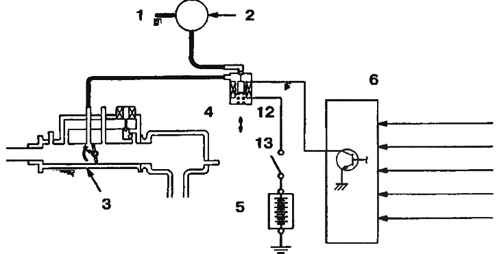
Pic. 6.5. Gasoline vapor recovery system diagram: 1 - From the fuel tank; 2 - Tank of the gasoline vapor recovery system; 3 - Throttle body; 4 - Solenoid valve for purge air control; 5 - Control relay; 6 - Engine control unit; 7 - Vacuum sensor 4G1; 8 - Engine air flow meter 4G9; 9 - Coolant temperature sensor; 10 - Inlet air temperature sensor; 11 - 4G9 engine atmospheric pressure sensor; 12 - OFF; 13 - ON
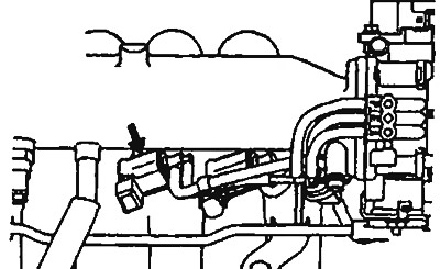
Pic. 6.6a. Location of the solenoid valve of the 4G1 engine gasoline vapor recovery system | 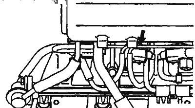
Pic. 6.6b. Location of the solenoid valve of the 4G9 MW gasoline vapor recovery system |
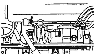
Pic. 6.6c. Location of the solenoid valve of the 4G9 engine gasoline vapor recovery system (except MW)