



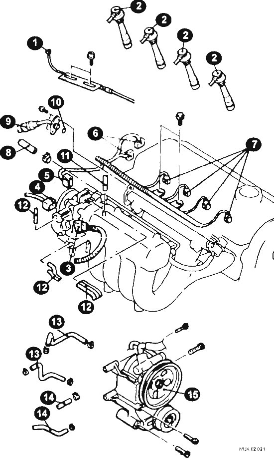
External engine components removed when replacing the gasket
1 - gas cable; 2 - spark plug wires; 3 - throttle position sensor plug; 4 - idle speed controller plug; 5 - gas pedal position sensor plug; 6 - ignition distributor plug; 7 - injector connector; 8 - fuel return hose connection; 9 - high pressure fuel hose connection; 10 - gasket; 11 - brake booster hose connection; 12 - Vacuum hose connection; 13 - connection of cooling system hoses; 14 - connection of heater hoses; 15 - bracket and power steering pump assembly.
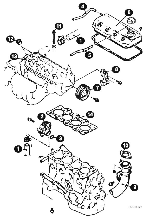
Internal engine components removed when replacing the gasket
1 - radiator hose connection; 2 - inlet pipe and thermostat in the housing; 3 - gasket; 4 - forced crankcase ventilation hose; 5 - ventilation hose; 6 - cylinder head cover; 7 - camshaft pulley; 8 - rear cover of the camshaft drive belt; 9 - intake pipe of the exhaust gas system; 10 - gasket; 11 - bolt; 12 - spark plug guide tube sealing ring; 13 - cylinder head assembly; 14 - cylinder head gasket.
Removal
Disconnect the ground cable from the battery.
Relieve fuel pressure in the fuel system.
Drain the coolant from the engine cooling system.
Remove the air intake hose and camshaft drive belt.
Disconnect the throttle cable.
Remove the high tension spark plug wire ends.
Disconnect the connectors from the throttle position sensor, idle speed control valve, gas pedal position sensor, ignition distributor and injectors.
Loosen the clamp and disconnect the fuel return hose.
(The original was published on the website mitsubishiman.ru)
Disconnect the high pressure fuel hose and remove the gasket.
Disconnect the brake booster hose.
Disconnect the vacuum hose.
Disconnect the cooling system hoses.
Disconnect the heater hoses.
Remove the bracket and power steering pump assembly with hoses.
Tie the disconnected power steering pump, complete with bracket and hoses, to the car body with wire.
Disconnect the radiator hose.
Remove the inlet pipe and thermostat housing assembly.
Disconnect the crankcase ventilation hoses.
Remove the cylinder head cover.
Having secured the camshaft pulley from turning, unscrew the mounting bolt and remove the camshaft pulley.
Remove the rear timing belt cover.
Remove the exhaust pipe and gasket.
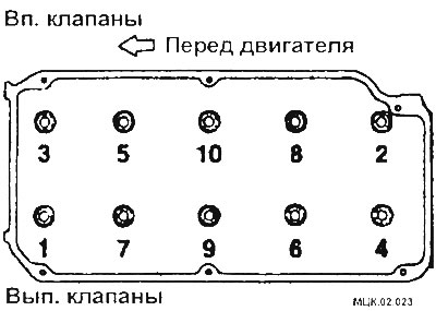
Loosen the cylinder head mounting bolts in 2 or 3 steps in the sequence shown in the figure.
Remove the spark plug guide tube sealing rings.
Remove the cylinder head assembly.
Remove the cylinder head gasket.
Examination
Check the mating surfaces of the cylinder head and block for deep scratches and other damage. If the defects are small, they can be removed by mechanical treatment. However, if the defects are significant, the parts must be replaced.
Using a metal ruler and feeler gauge, check the flatness of the mating surfaces.
Clean the bolt holes in the block.
Installation
Installation is carried out in reverse order, taking into account the following:
Degrease the mating surfaces of the gasket.
Before installing the bolts, check the length of the bolt shaft (to the head), which should not be more than 96.4 mm. If this size is exceeded, the bolt must be replaced.
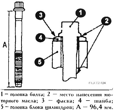
Before installation, lubricate the top surface of the washer and the bolt threads with a small amount of engine oil.
Tighten the cylinder head bolts in five steps in the sequence shown in the illustration.
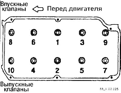
- Step 1 - tighten to 80 Nm;
- Step I - completely loosen all bolts in the reverse order shown in the figure;
- Step III - tighten to 20 Nm;
- IV-V techniques - apply marks with paint (on the bolt heads and cylinder head and turn 90°).
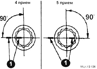
The marks on the bolts and cylinder head must be in line.
CAUTION: Always tighten the bolt at an angle exactly equal to 90°, otherwise the cylinder head mounting bolt may become loose.
Before installing the coolant supply pipe, remove the supply pipe mounting bolt and install the pipe. Screw the bolt back into place (arrow).
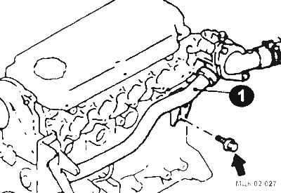
When installing the inlet pipe and thermostat assembly, apply a 3 mm diameter bead of sealant (1) to the mating surface of the inlet pipe (2).

After inserting the thermostat housing into the cooling system supply pipe, tighten the cooling system supply pipe mounting bolts.
When installing the camshaft pulley, secure the pulley from turning with a special tool
When installing the high-pressure fuel hose (2), lubricate the O-ring 3 with a small amount of clean engine oil.
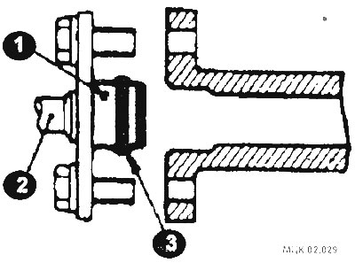
While slightly turning the fuel hose flange right and left, carefully insert it into the fuel manifold to avoid damaging the O-ring seal.
Install the camshaft drive belt.
Install the air intake hose.
Fill the cooling system with coolant.
Adjust the throttle cable.