



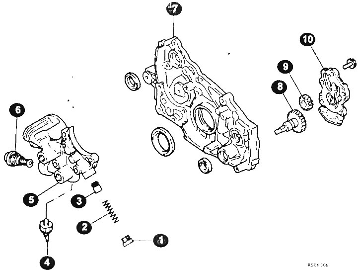
Oil pump components
1 - cork; 2 - spring; 3 - piston of the pressure reducing valve; 4 - oil pressure sensor; 5 - oil filter bracket; 6 - oil cooler bypass valve; 7 - front cover; 8 - leading gear; 9 - driven gear; 10 - oil pump cover.
Disassembly
Remove the oil pump from the engine. To remove the pump, it is necessary to disconnect and remove the camshaft drive elements (lower part), as well as the oil pan.
Clean the removed oil pump from dirt, wash the external elements of the pump and covers.
Disconnect the oil receiver from the pump body (if not already disconnected).
After unscrewing the mounting bolts, detach the pump housing from the front cover of the cylinder block.
Remove the pressure reducing valve (plug, spring and valve).
Clean all parts from dirt, oil and deposits.
Stubborn deposits can be removed by soaking the parts in solvent.
CAUTION: To avoid poisoning, avoid inhalation of solvent and contact of solvent with exposed areas of the body.
Checking oil pumps with internal gear engagement
Check for foreign particles and determine the cause of their entry.
Check the pump body and cover for cracks and scratches. If there are any defects, replace the body.
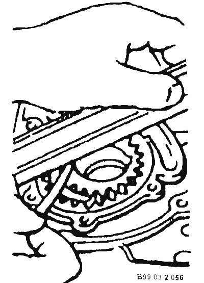
Reinstall both gears into the pump body and check the axial clearance between the upper side of the pump body and the upper side of the gears by applying a steel ruler and measuring it with a feeler gauge as shown in the figure. The maximum allowable clearance is 0.10 mm between the ruler and the inner gear and 0.15 mm between the ruler and the outer gear of the pump. If necessary, the axial clearance can be slightly reduced by processing the pump body on a straightening plate using sandpaper.
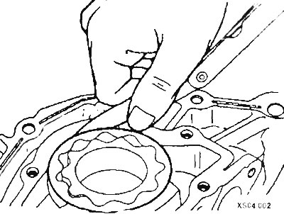
Insert a feeler gauge between the outside of the pump drive outer gear and the hole in the housing. The gap should not exceed 0.20 mm.
[Original version of the article on the website www.mitsubishiman.ru]
The gap between adjacent teeth should be less than 0.18 mm.
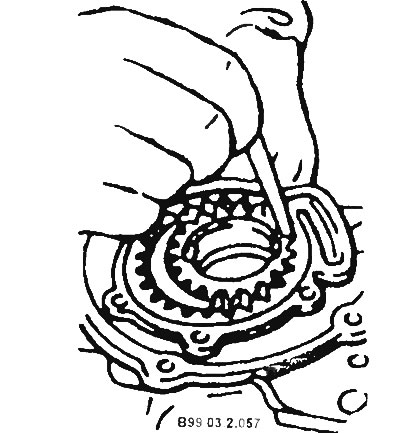
If the measured values exceed the permissible values due to wear, either the pump gears or the oil pump housing must be replaced.
Check the pressure reducing valve for scratches and signs of sticking. Dents and burrs should be removed with a fine grinding stone.
Check the pressure reducing valve spring for loss of elasticity and bending. If there are any defects, replace the springs.
Check the inlet pipe assembly with the filter (mesh) for leaks and damage to the mesh inlet filter.
Check the gears for chipped material, scoring and wear.
After installing the gears and front cover, check that the gears rotate smoothly.
Check the axial clearances of the gears. Required values: leading gear no more than 0.14 mm; driven gear no more than 0.12 mm.
Assembly
Lubricate all internal parts of the pump with engine oil.
Install the pump gears by aligning the marks.
CAUTION: To avoid engine damage, coat all cavities of the oil pump with grease before installing the gears to ensure oil suction and supply to the engine lubrication system.
Install the cover and gasket.
CAUTION: To avoid engine damage, use only original factory gaskets.
Install the pressure reducing valve and spring.
Using a torque wrench, tighten the pressure reducing valve plug to 30 Nm.
When repairing the oil pump, replace the oil filter and replace the engine oil with fresh oil.
CAUTION: If the oil pressure is not immediately established at the normal level, the oil pan should be cleaned and the connection of the pump to the inlet pipe should be checked. If necessary, dismantle and disassemble the pump, fill the pump cavities and reassemble the pump. Running the engine without oil pressure will cause serious damage to the engine.